
The tensioner rod primary function is to hold the tensioner in a retract position. When unlocked from the retracted position, the locking mechanism slide around the rod as the tensioner spring pulls the tensioner mechanism into position. This position is determined based on the blade force contact with the timing chain and the force of the spring pull of the tensioner spring.
At this point there is nothing but the spring keeping the timing chain tensioned. The rod keeps the tensioner locked against the chain, and that is why you have to unlock it with a screwdriver (or similar tool) via the tensioner hole in order to release it.
Note the locking mechanism sliding around the tensioner rod moves in one direction only. Once the locking mechanism reaches the tensioners position against the timing chain, the locking mechanizing prevents the tensioner from being retracted without releasing the locking mechanism.
Under normal conditions, I do not believe this tensioner rod or the locking mechanism has any function in keeping the timing chain tensioned. Because the locking mechanism will always allow the rod to move in one direction, it would provide compensating force to the blade against the chain if necessary, as the chain wears. That said, I believe the real reason for designing the locking mechanism to lock and to move in one direction only is to protect the engine in the rare occasion where the tensioner spring fails. In that case the locking mechanism would hold the tensioner in its pre-determined position, with the curved blade forced against the timing chain thus preventing the timing chain from coming off or jumping its sprockets.
Although absolutely not recommended, the tensioner can function without the locking pin. The real force against the chain is the spring. When the tensioner is released it is the spring that pulls it into position, and it is the spring that keeps it there. The lock mechanism will move forward with the spring but will not move back.
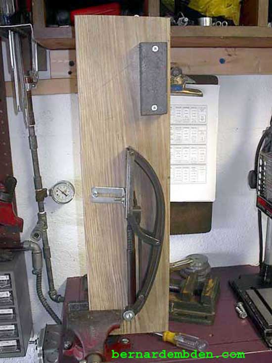
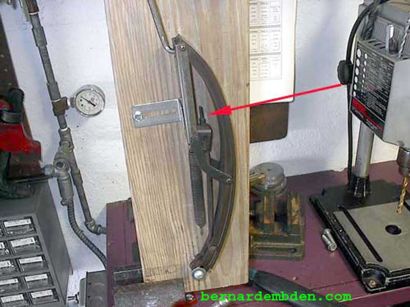
I believe that knowing exactly how the V-12 Jaguar timing chain tensioner works is vital to properly retracting and locking this tensioner. Below is a photograph of a tensioner sent to me my John Testrake. Although it is in working order, my advice is always to replace this part whenever you have access to it. I mounted his tensioner on a jig that approximates its position in the engine and allows me to photograph the full range of its operation. A piece of "U" shaped iron stock bolts to the top of the jig to allow leverage for the retract tool.
The tensioner (with spring attached) was retracted and released 20 times. The results were noted. The process was repeated in two additional 20 (retract and release) sets. The results are an average of the three 20 set operations.
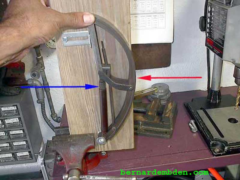
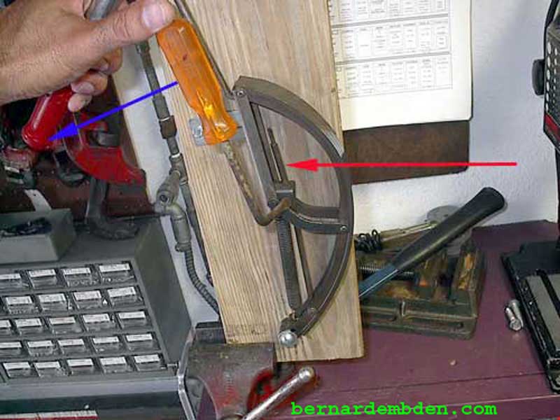
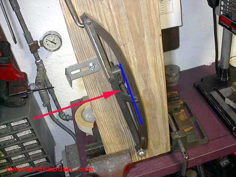
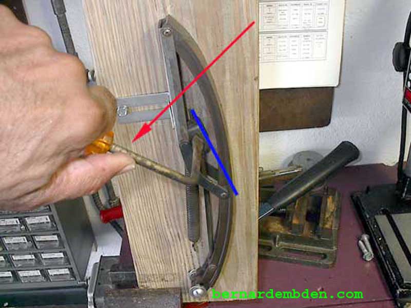
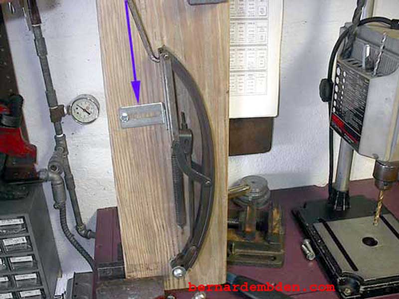
The tensioner (photograph below) is in the full "compress" mode. In this mode the spring (blue arrow) pulls the tensioner mechanism down resulting in the flexible "blade" being forced into a "bow" or "arch" (red arrow). This flexible material is forced against the timing chain, thus eliminating any timing chain "slack" and applies the proper tension to the chain.
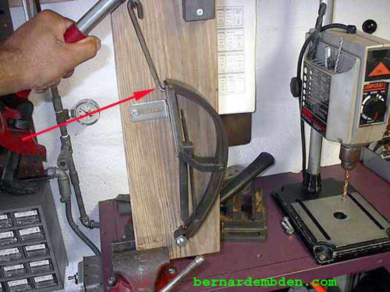
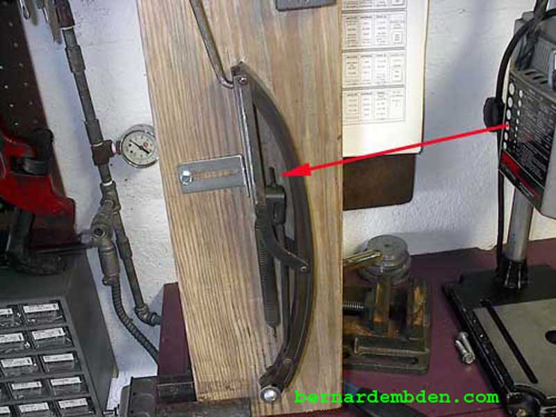
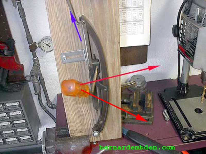
The tools necessary to retract the tensioner can be fabricated easily. I am using a modified paint scraper and a large flat washer attached to a "hook" made by using an old screwdriver and heating and bending the end. This "hook" accesses the appropriate opening (red arrow photograph below) in the tensioner.
Note that the opening in the tensioner where this "hook" attaches would be accessed from the area below the cam sprocket on the right side of the engine once the valve covers were removed.
To retract and lock the tensioner, I recommend the following steps:
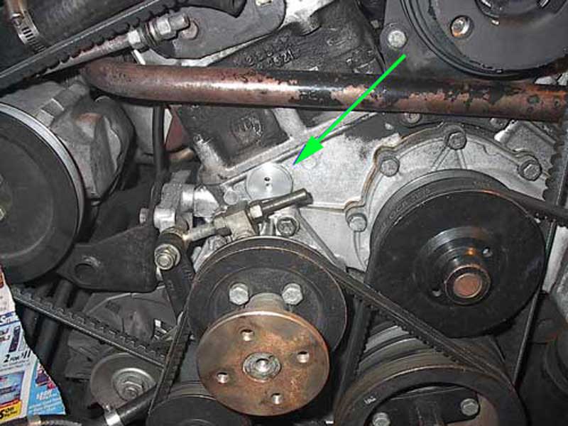
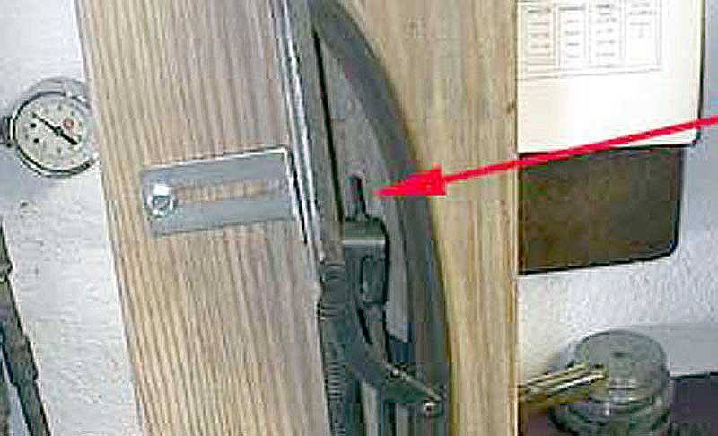
1) Remove the plug from the timing cover that allow you to access the tensioner locking catch. (green arrow photograph below). Note that the original rubber plug has been replaced with a custom aluminum plug.
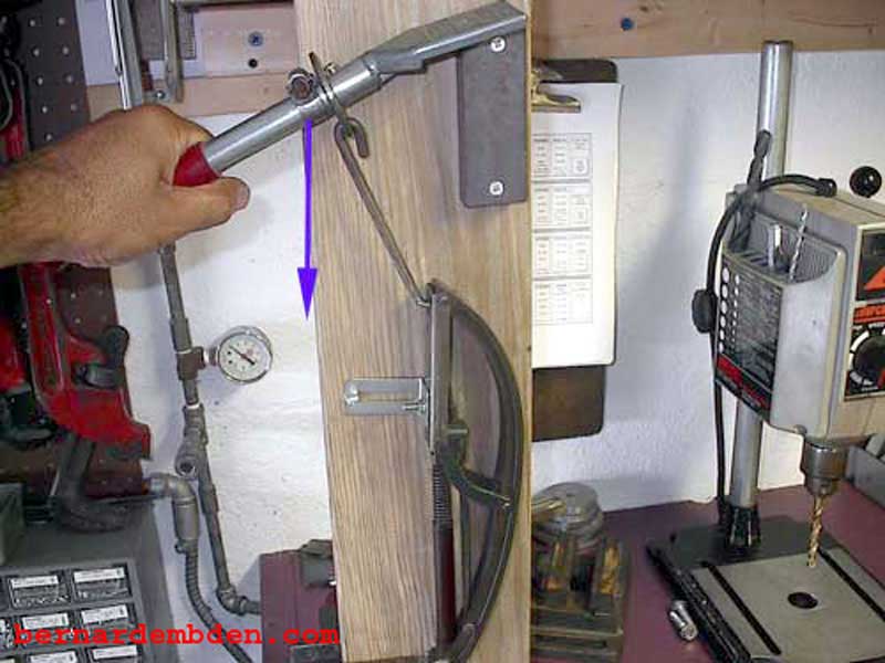
2) Release the tensioner's locking catch (via the timing cover) by using a fabricated tool (a 90 degree bent screwdriver). The lock is released by twisting (anticlockwise) in the direction of the blue arrow, (see photographs below). Note that it’s possible that you might have to twist it in both directions to release the locking mechanism.
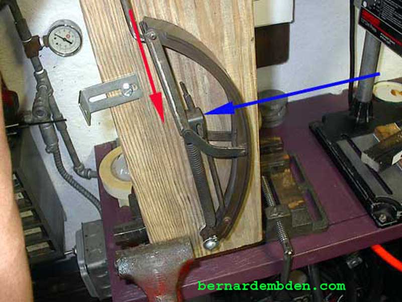
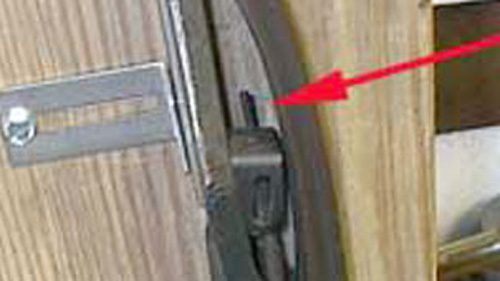
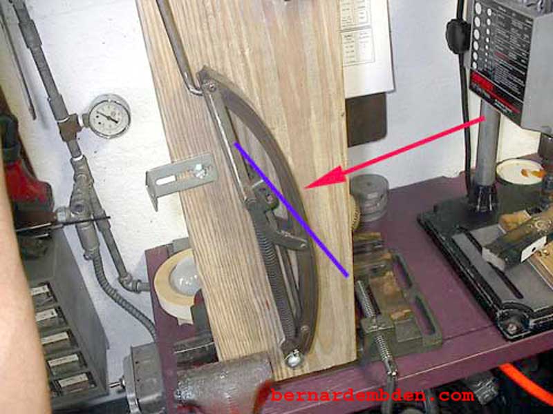
2) The tensioner is then retracted by pulling on the top of the tensioner via the "hook". Note also that the locking pin is bent. (red arrow). This possibly resulted from the tensioner being in the "locked" position for an extended amount of time.
You should not simply retract the tensioner as is. Do not force it.. Instead, first (or simultaneously) release the locking catch via the plug in the timing chain cover. The ROM states that once the locking catch is activated, the tensioner can be retracted. This is not completely accurate.
During three sets of 20 consecutive retractions the tensioner would always retract, (as per the ROM) once the locking catch was activated, provided the retraction was continuous and smooth. Stopping the retraction or allowing the tensioner to compress would always activate the locking catch. The locking catch would then have to be "unlocked" before the tensioner would continue to retract.
Based on the preceding tests, the recommendation is to unlock the locking catch and keep it unlocked my maintaining constant anticlockwise force (blue arrow) during the full and complete retraction of the tensioner.
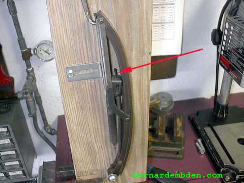
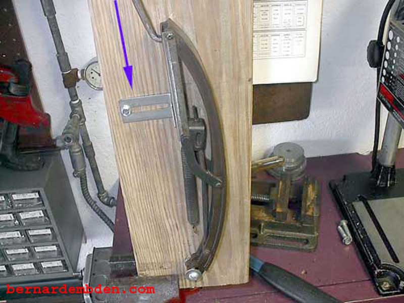
A significant amount of force is needed to retract the tensioner. The photograph below shows the locking pin's "shoulder" (red arrows) on the locking pin. The tensioner must be retracted until this "shoulder" retracts below the "locking catch" as the following photographs show.
If at any time during the retract procedure the process is stopped or the tensioner is allowed to compress, the locking catch will lock to the locking pin and the tensioner cannot be retracted unless the locking catch (blue arrow) is again released.
Once the locking pin shoulder is below the locking catch, the tensioner should automatically "lock". In the photograph below the tensioner is fully retracted. As the tension is released the locking catch is supposed to pivot and catch on the shoulder of the locking pin.This is not always the case. In three sets of 20 consecutive retract simulations, the locking catch only worked an average of six times per set (30%). Of those average six "locks" four were so marginal in terms of how much metal of the locking pin shoulder that was actually engaged in the locking catch, that any unusual vibration would almost certainly unlock the tensioner, with disastrous results.
Notice the position of the locking catch (blue line photograph above). In the photograph above the tensioner is fully retracted, however the locking catch (blue line) is still parallel with the locking pin. (red arrow).
It has not locked automatically.
The photograph below shows the locking catch being manually "locked" on the shoulder of the locking pin by using the bent screwdriver. Note the angle of the locking catch (blue line), it’s no longer parallel with the locking pin.
To complicate matters, this is all done somewhat "blind" as this process cannot be seen from the top of the engine with the valve covers off.
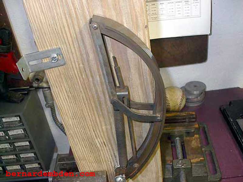
In the photograph below the bend screwdriver has been removed. The tensioner in now in the "locked" position. Note angle of the locking catch (purple line). Also note that the tensioner "blade/arch" (red arrow) is almost vertical, away from the timing chain. This would now allow you to remove the cam sprockets or remove the tensioner if access permitted.
My recommendation is to manually "lock" the locking catch by maintaining the tensioner's full "retract" position while the locking catch is activated by using the "tool" through the timing cover and twisting in an anticlockwise direction.
This is important. By keeping the locking catch fully released (applying anticlockwise tension) during the complete tensioner retract process, you can "feel" when the locking catch engages and locks at the top of the locking pin.
The locking catch will move slightly more in the anticlockwise direction when it locks onto the shoulder of the locking pin.
The recommendation for retracting the tensioner is to unlock the locking catch and keep it unlocked my maintaining constant anticlockwise force during the full and complete retraction of the tensioner. Once the tensioner is fully retracted, tension must be maintained on the locking catch until it positively locks on the shoulder of the locking pin by moving slightly more in the anticlockwise direction.
Releasing the tensioner is a reverse of the retract procedure. First the tension is removed from the locking catch by pulling up the top of the tensioner via the "hook" of my tensioner retract tool (blue arrow). With the spring tension released and maintained, the locking catch is released from the pin shoulder by twisting clockwise with my 90 degree screwdriver. (red arrows photograph below).
With the locking catch released from locking pin shoulder, the tensioner can be slowly released. There is a small possibility that the locking catch can get hung up on the locking pin during the release process. Therefore: I recommend that the locking catch is released, and held, while the tensioner is released.
Notice the "blade" of the tensioner becomes more convex as the tensioner is retracted. This would force the blade against the timing chain to produce the desired effect of eliminating slack and applying the proper tension. (photographs below)
Tension completely relieved from tensioner. This is the normal position in the engine.
It's important when retracting the tensioner that you visualize what the tensioner mechanism is doing. A mistake while retracting or releasing this part will not only ruin your day, it might ruin your year.
