
After 25 years, the engine idle control on my 1978 Jaguar XJ-S was no longer functioning properly. Idle speed could not be reduced to the 750 RPM that the car required. The problem was the auxiliary air valve, (AAV) a water temperature control device that Jaguar uses to control idle speed up to and when the engine reaches operating temperatures. To function, the auxiliary air valve routes filtered air from the rear of the air cleaner assembly directly to the intake manifolds, bypassing the throttle plates. As the engine warms up the airflow is gradually reduced until, at operating temperatures, the airflow is greatly reduced or stopped. The auxiliary air valve connects to the air cleaner assembly via a one-inch I.D. hose. Testing of this hose indicated no measurably difference in cold start and warm up functions if the hose size was reduced to 5/8 inch.
In addition, I was convinced that, because of the location and design of the AAV, air passing through the AAV did not evenly flow to both intake manifolds, thereby producing different intake manifold vacuum levels.
My plan was to rebuild or replace this valve. It’s not complicated. A wax bulb reacts to temperature and varies the air opening. The more I thought about it, the less enthusiastic I was. What if I could replace it with a simplistic cable that would never need replacing?
I longed for the days when a simple, manual cable controlled this "warm up" function. This was also a unique opportunity to simplify an overly complicated automobile.
The objective was simple:
Discard the AAV completely. Design and install a manual device that would allow not only cold start adjustability, but also equal airflow to both intake manifolds during the entire "warm up" period.
This device would operate via a manual cable, similar to the manual choke cables that were used with old carburetors.
Photographed below are:
Generic replacement choke cable available from most automotive parts and mail order stores.

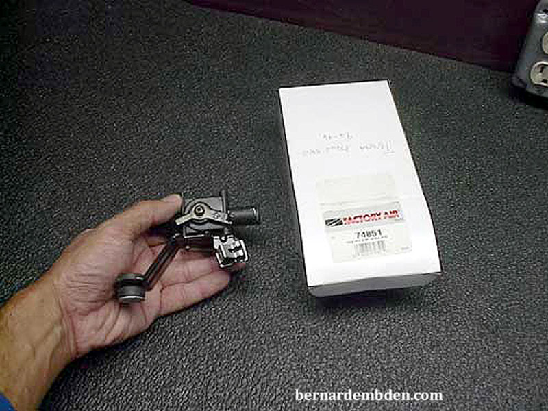
(Photographed below) Manual water heater control valve (generic part number 74851) designed for a 1992 to 1996 Toyota. The selection of this valve is critical. The I.D. must be a minimum of 1/2-inch (this valve is 5/8-inch) and the controls must be at 90 degrees to the body of the valve. This configuration is necessary for cable routing.
Note: This valve is manufactured by Four Seasons. Description: Heater Control Valve, part number 74851. It should be available from a number of automotive parts suppliers on the Internet.
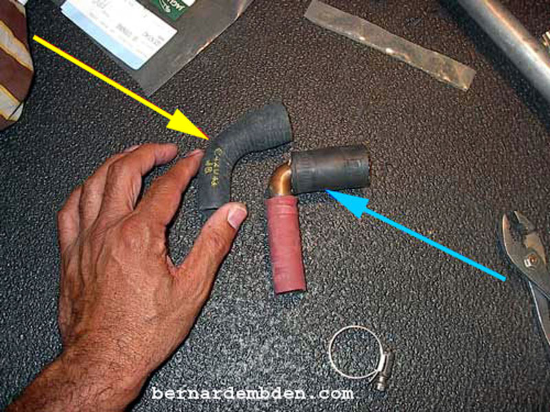
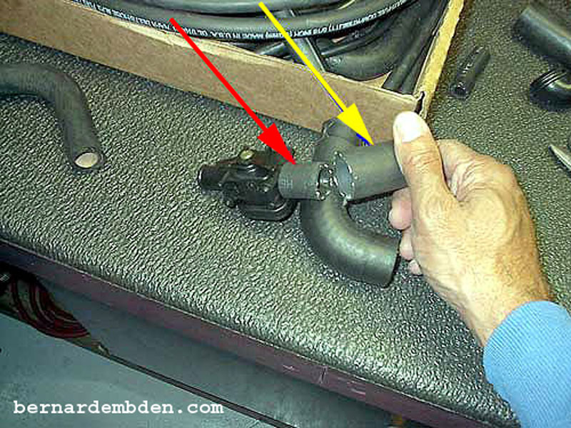
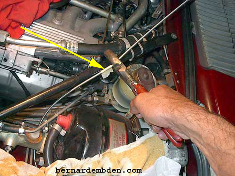
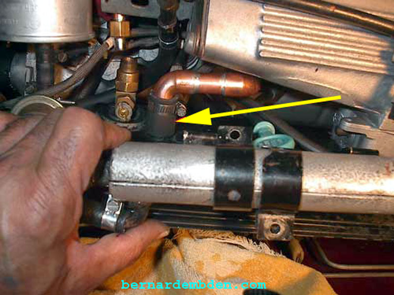
Manifold balance pipe 90 degree hose elbow. (yellow arrow Jaguar part number 02C42042 photographed below). If this part is unavailable, a substitution elbow can be made from 1/2 inch copper pipe and hose. (light blue arrow).
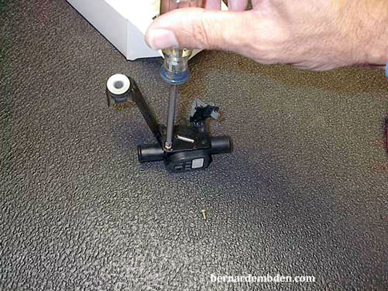
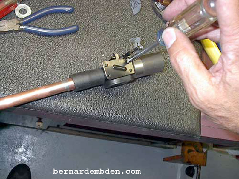
The bracket would have to be modified to fit in the existing space. Remove the two screws that hold the bracket to the control valve.
Cut the bracket as per photograph below.
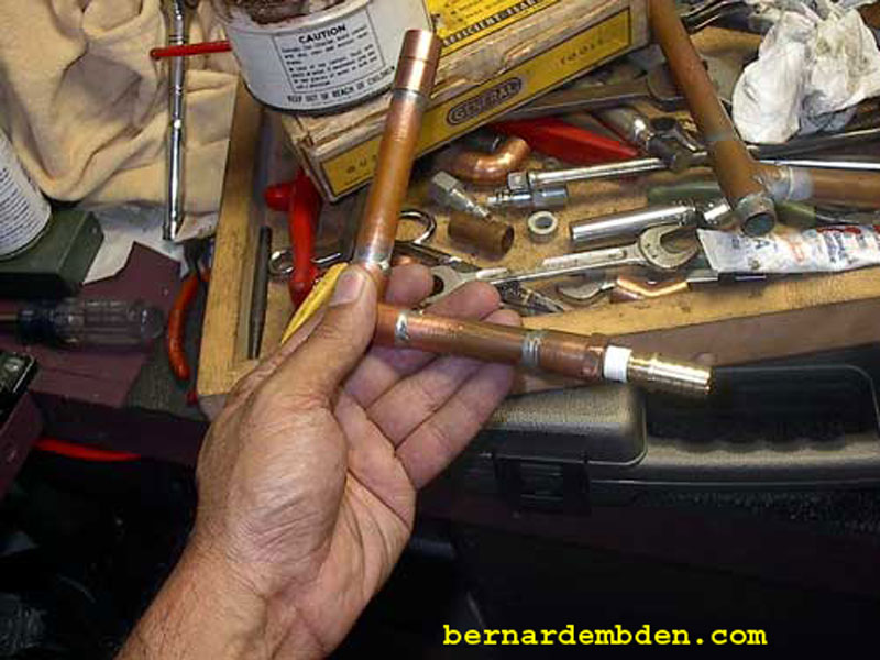
The auxiliary air valve has a 1" I.D. opening. The Toyota valve has in I.D. of 5/8 inch. Testing indicated that 5/8" was more than adequate to handle the airflow necessary for my modification. To transition the 5/8" to 1" connection, I installed a 5/8" heater hose over the control valve connection. (red arrow photograph below). I then installed a short piece of 1" hose over the 5/8 hose (yellow arrow). Although this device sees vacuum, not pressure, it needs to be "vacuum tight". Note that the heater control valve flow is directional. An arrow on the side indicates direction of flow.
The modified bracket is then installed on the manual control valve.
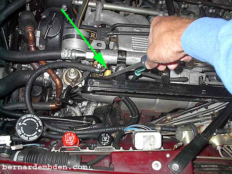
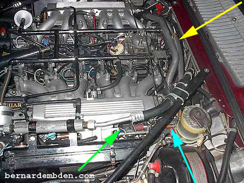
Due to the planned location of the new valve, the original 1-inch air pick up connection at the back of the air cleaner could not be used. There is a smaller (5/8-inch) connection at the front of the air cleaner (green arrow, photograph below). This would provide the filtered air necessary for my project.
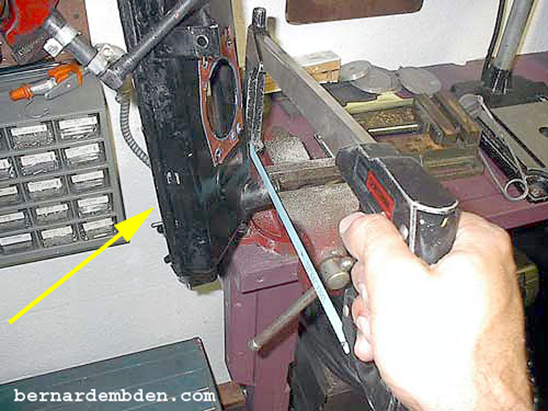
Remove air cleaner housing (yellow arrow photograph below) and cut approx. 3/8 inch from the auxiliary air valve hose connection. This is necessary to adequately clear the manual control valve.
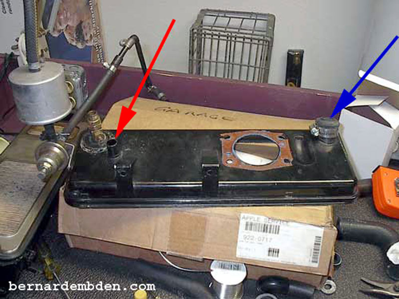
Photographed below is the air cleaner housing. The original auxiliary air valve connection (blue arrow) has been cut and capped. The smaller connection (red arrow) will be used for the manual control valve's filtered air source.
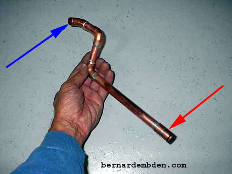
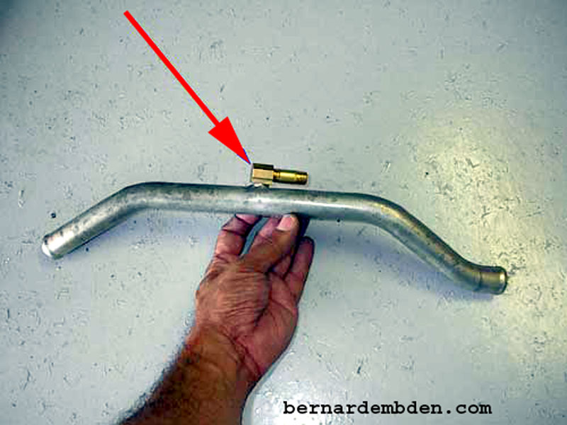
I could have used a 5/8-inch hose to connect from the manual control valve to the air cleaner connection. However, copper does look so much better. I fabricated a custom pipe from 1/2-inch copper tubing. The top connection (blue arrow) will connect to the air cleaner housing's new air source. The bottom connection (red arrow) connects to the inlet of the manual control valve. (photograph below).
Another fabricated pipe (pictured below) will attach to the exit of the control valve,
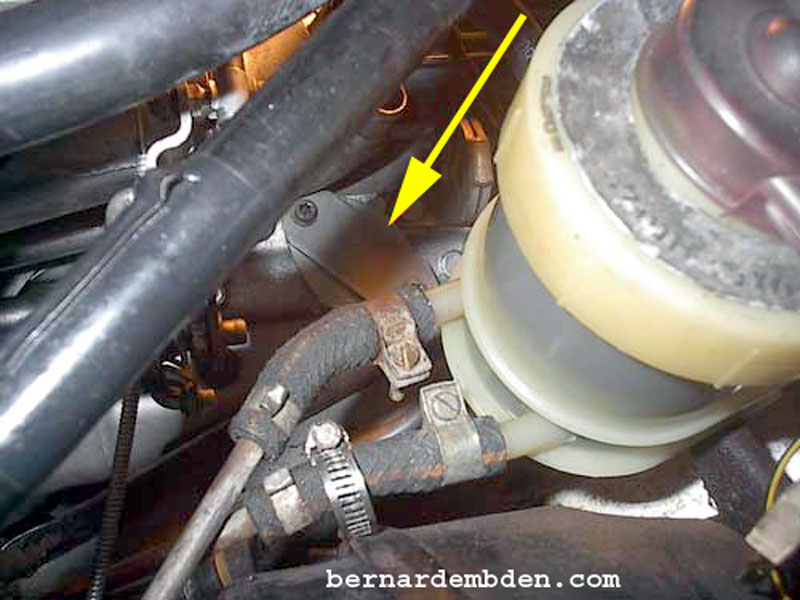
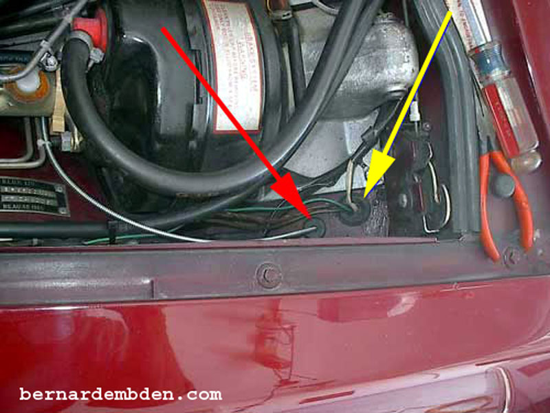
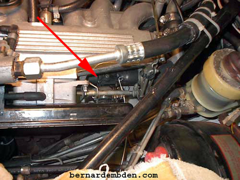
The AAV, now redundant can be be removed. Remove the two bolts securing it to the engine. (yellow arrows photographs below).
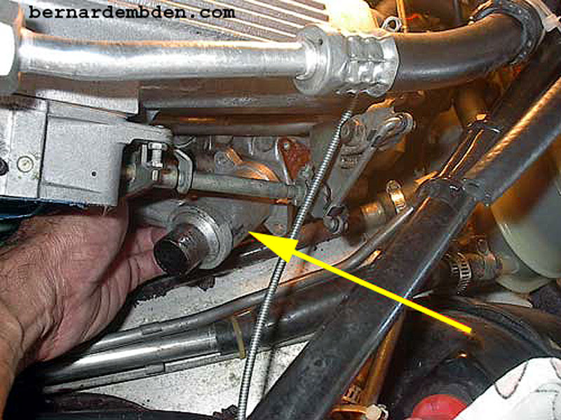
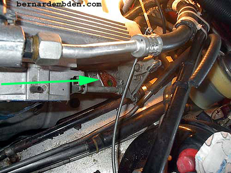
As long as the radiator cap is untouched, the radiator does not have to be drained for this procedure. As seen in the photograph below (green arrow) virtually no antifreeze drains from the removed AAV.
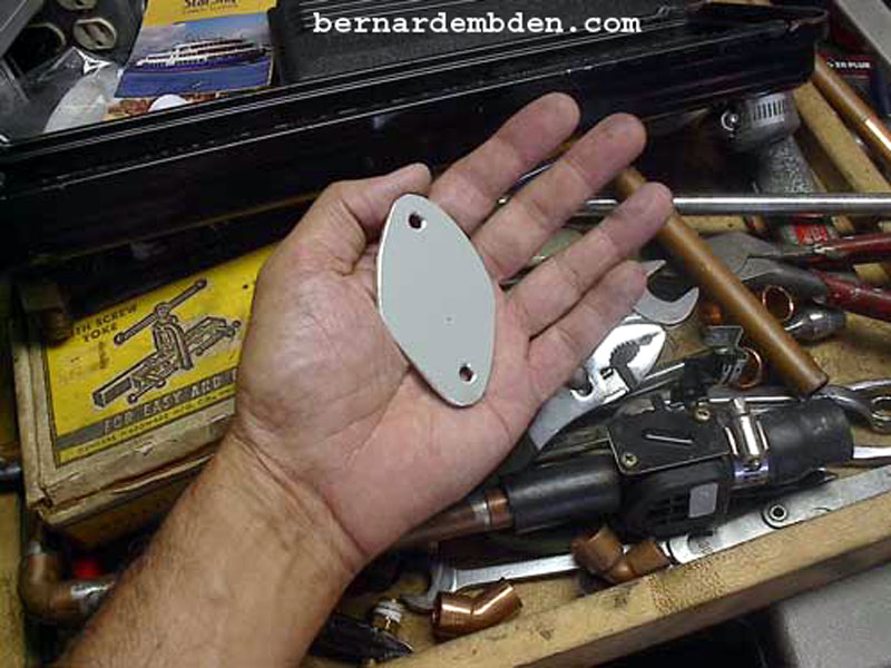
The AAV opening will have to be sealed. I fabricated a blank plate from 1/8 thick aluminum stock.
![]()
(Photograph below) I made a strap from metal stock (red arrow, probably overkill) and placed it on top of the blank plate. (yellow arrow).
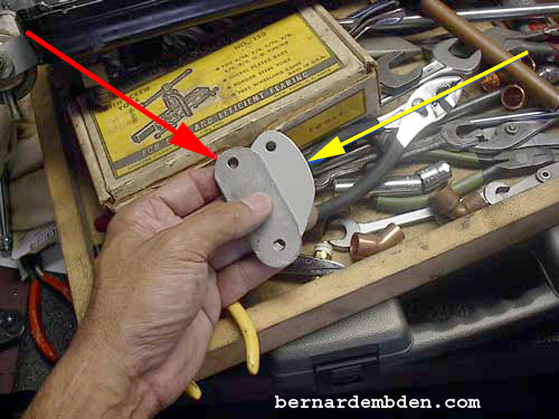
I re-used the existing gasket, just added gasket cement and installed the blanking plate. (yellow arrow)
The photograph below shows the modified balance tube. I drilled a hole mid-point on the back of the tube. A 1/2-inch I.D. right angle tap was silver soldered at this mid-point. (red arrow). This is where the air from the idle control device will be fed, thus ensuring that both engine banks will receive equal amounts of air.
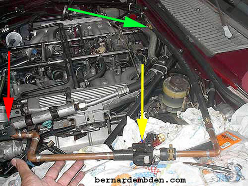
The photograph below shows how the assembled idle control device will be installed. The red arrow is the filtered air intake from the air filter. The yellow arrow is the air valve. The green arrow identifies the manifold balance tube connection. It will feed air at the midpoint of the balance tube, ensuring that both banks get idle air equally.
This device is designed to be controlled via a generic "choke" cable. Finding a suitable location inside the car for the cable control knob was a bit of a challenge. I could bolt the control knob anyplace under the dashboard, route the cable through the existing firewall harness opening and it would work.
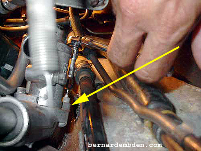
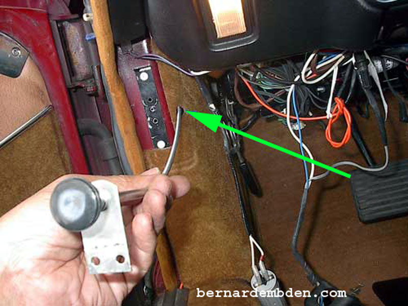
You know that that was not acceptable to me, after all, this must not only work, it must look good. I wanted the control knob adjacent to the fuel pump inertia cut-off switch, with the cable completely hidden. This required a 12" drill bit (yellow arrow photograph below) to make holes for the cable behind the mounting location and completely through the boxed panel. (green arrow).
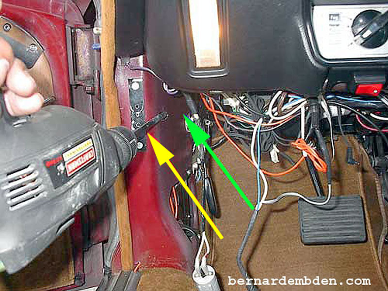
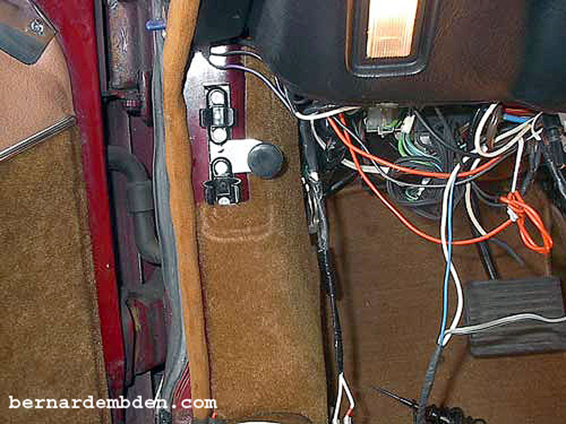
A corresponding hole was made in the kick plate upholstery (green arrow). This allows the cable to be concealed and the control knob to be installed in the desired location, adjacent to the inertia switch bracket.
(Photograph below) In order to get a reasonably straight run through the firewall, I removed a rubber plug (red arrow) and drilled a hole 1 inch down and to the right of the existing wiring harness. (yellow arrow).
The control knob bracket should be bolted to a secure location. This allows precise movement of the cable. One hole of the fuel cut off bracket aligned with one hole of the control knob bracket. I drilled and tapped the other hole.
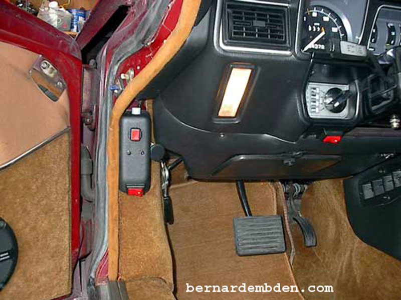
Photograph below. Manual idle control knob installed. If installed properly, it should look original, as if the interior was designed that way.
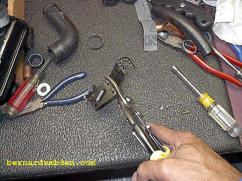
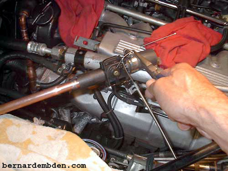
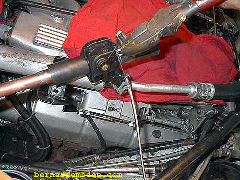
Back to the engine compartment. Measure the cable carefully (yellow arrow photograph below) and cut off excess cable housing. The cable and housing cannot be cut at the same length. Make sure the cable is pulled in from the housing before cutting.
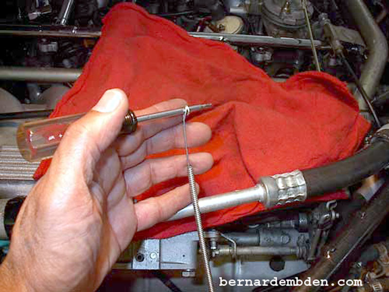
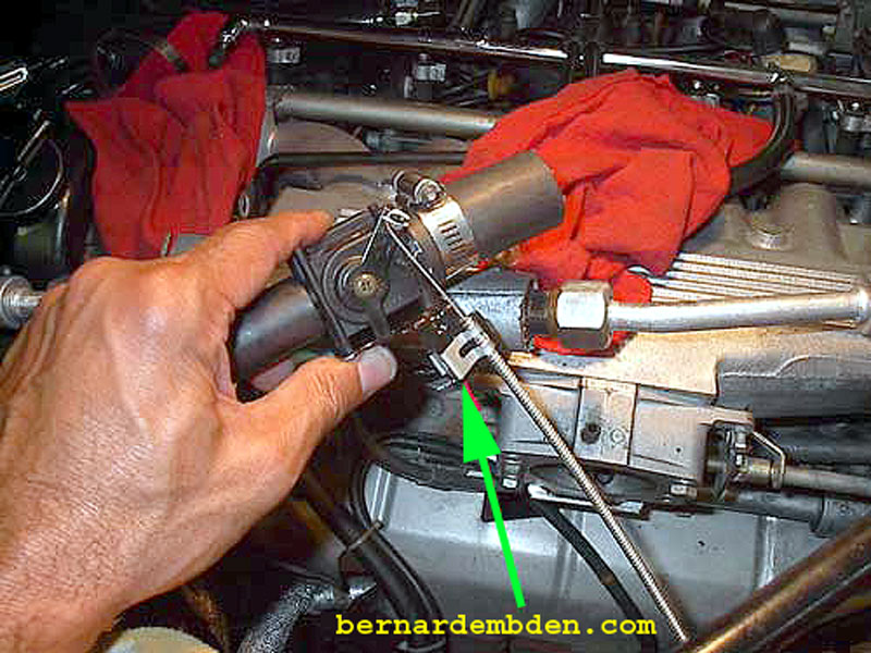
From inside the car, push the control knob in completely. Move heater control valve to fully closed position. Measure and bend cable around control valve's lever. (photograph below).
Note the photographs below. The cable should be bent in a circle. This allows the cable to rotate on the control lever as the lever arcs through the open/close cycle. This ensures a consistent smooth operation.
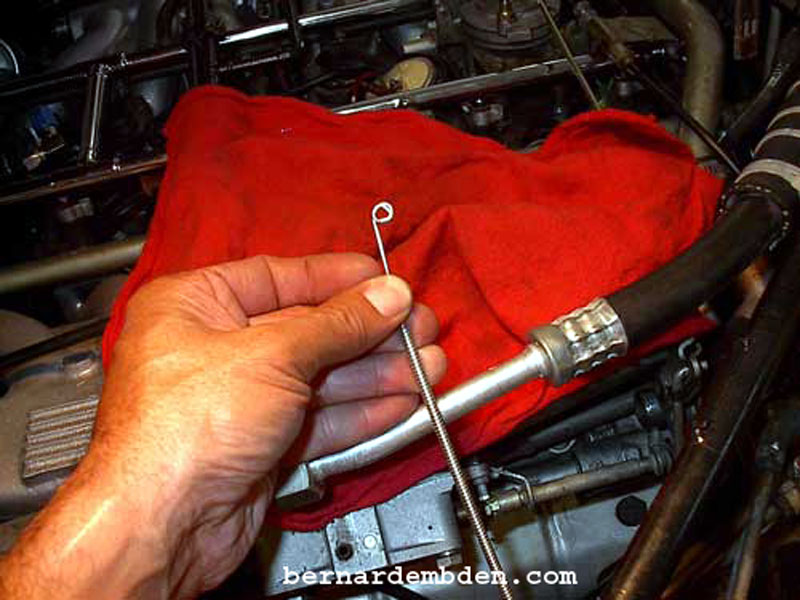
Install control cable and bend the lever's tip to prevent cable from sliding off.
A snap in metal "clamp" holds cable housing in place. (green arrow photograph below).
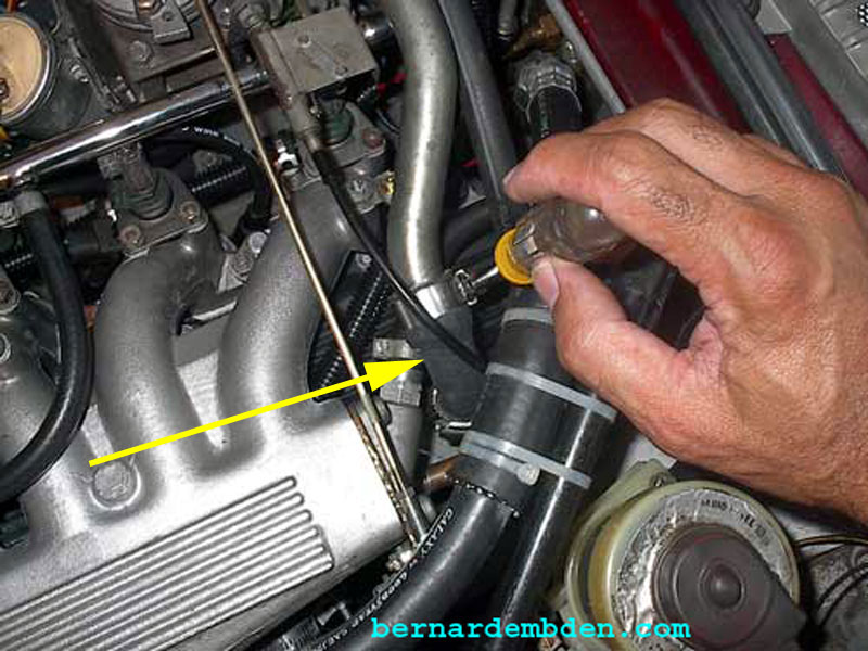
(Photograph below) Connect new filtered air source. (yellow arrow).
Install air balance pipe. Attach air balance pipe rubber elbow. (yellow arrow photograph below. Jaguar part number 02C42042).
Position and tighten idle control device (red arrow photograph below) and associated clamps. Attach fabricated 90-degree copper pipe to exit of valve. Attach hose from pipe to the midpoint of the manifold balance pipe.
Manual warm up idle speed control project completed.
Photograph below. Idle valve (green arrow). 90 degree copper pipe at exit of idle control valve (light blue arrow) Air introduced at mid-point of balance tube (yellow arrow). Total cost $35.00 dollars US.
For me, this was a worthwhile project. It completely replaces an obsolete, problematic part with a simple, permanent solution.
The procedure for starting now is:
Pull ("choke") cable out.
Start automobile. If necessary, use cable to adjust idle.
Does this bring back memories or what?
