
There are a number of repair procedures that can only be accomplished if the front suspension cradle is removed. Unfortunately the primary function of this cradle is to support the engine. The Jaguar Factory offers an engine support device. Since I was not about to actually purchase this device, I decided to fabricate one.
If you decide to fabricate this engine support, do so at your own risk.
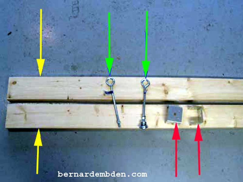
I visit to my favorite store, Home Depot in the US, allowed me to acquire all the raw materials I needed. (photograph below)
1) A single 6x2 inch wood beam 12 feet long, cut in equal halves. (yellow arrows)
2) Two 1/2 inch eye-hooks 12 inches long with nuts and washers. (green arrows)
3) Two metal brackets used to secure 4x4 posts. (red arrows)
Not showed, 12 inch long angle iron, carpenters glue and a box of wood screws.
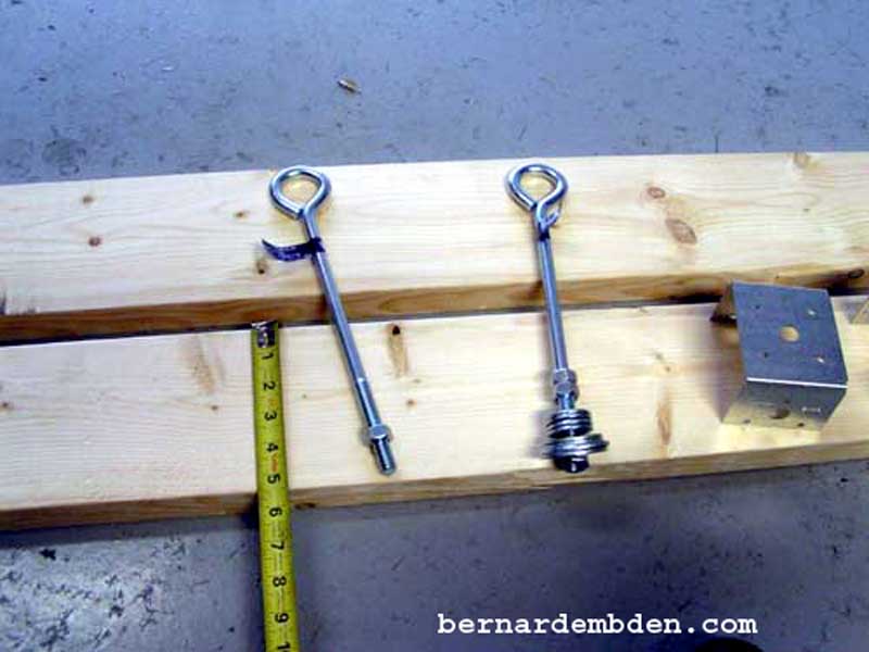
Photograph below. The eye-hooks will be responsible for supporting the engine. I used 1/2-inch hooks. They must be at least 12 inches long.
Assembly the wood beams in two identical 6-foot lengths. Placing the 6x2 inch wood beams on its end, and using 1/2 inch plywood stock as spacers, (red arrow photograph below) screw the two pieces of lumber together at each end.
![]()
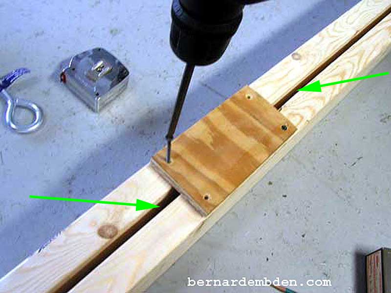
In order to keep the exact spacing along the entire length of the wood beams I attached a center support with four wood screws, making sure to maintain the 1/2 inch spacing. (green arrows photograph below).
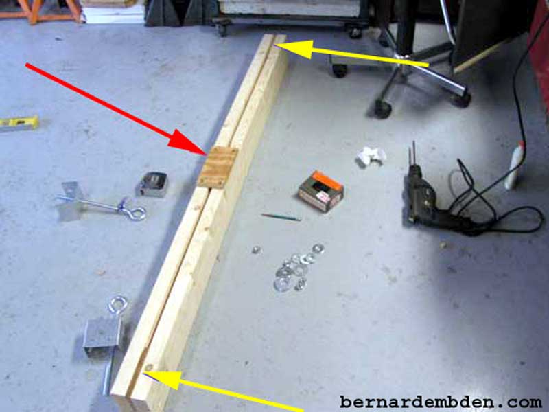
Photographed below is the completed support beam structure. The beams are screws together at both ends (yellow arrows) and the center (red arrow). I was not exactly sure of the load rating, however with the 6x2 beams assembled on their ends I was convinced it was more than enough to support the engine.
The engine support needs somewhere to rest. I fabricated "feet" (green arrow photograph below) designed to fit in the "gutter" where the fender bolts to the frame. This device was designed to support the engine. The support "feet" needed to be as wide as the gutter location would permit. In addition I wanted the support beams level. Starting with 2x2 inch wood stock I modified it to fit in the gutter location while the top was level to the garage floor.
Note: The front of the support "feet" can be no more than two inches measured from the base of the fender "gutter". Any higher and the 12 inch eye hooks might not reach the engine pull brackets. Finally both "feet" needed to be the same dimensions.

Once the feet modifications were completed, I temporally installed the support feet and wood beams on the car. The beam location needs to be exactly above the engine support brackets. I then marked the feet’s exact locations, front and back in relationship to the beams. (yellow arrows photograph below) These locations are critical. The space between the wood beams must be centered directly above the engine support brackets that the eye-hooks will connect to.
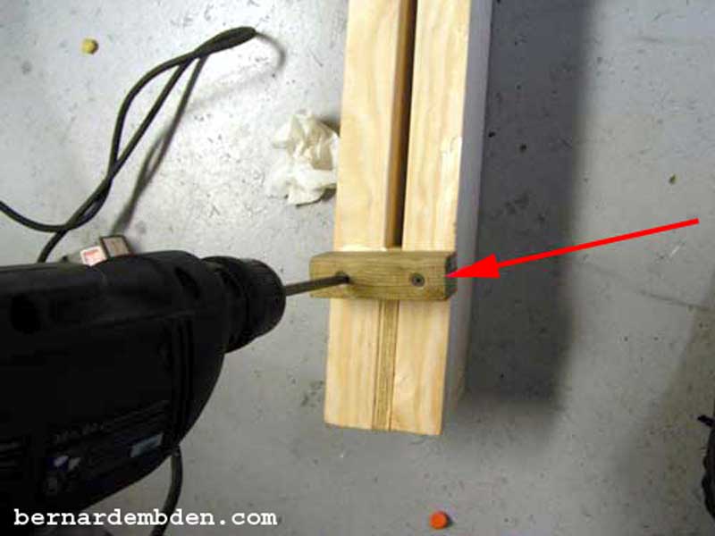
Using screws and glue, I installed the support feet to the wood beams at the exact, marked locations. Although not necessary, I used wood glue at all join locations. Note that the support feet are at an angle to the support wood beams. This reflects the angle of the fender gutter at the location the support will be used. Counter-sink all screws to protect the fender gutter. (red arrow photograph below) .
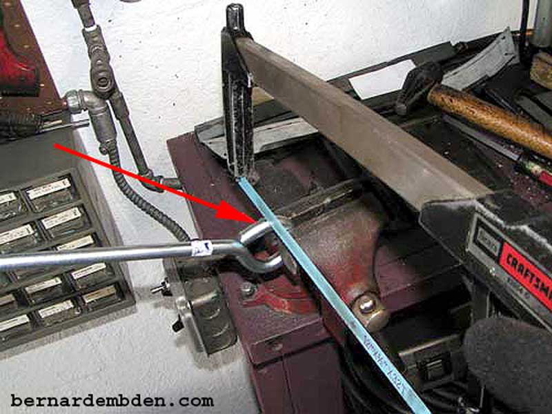
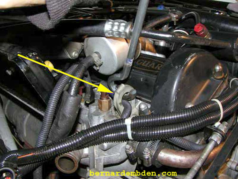
The eye-hooks I purchased were closed. In order to be able to hook them to the engine support brackets, they would have to be opened. Using a vise I cut approximately 1 inch off the ends. (red arrow photograph below).
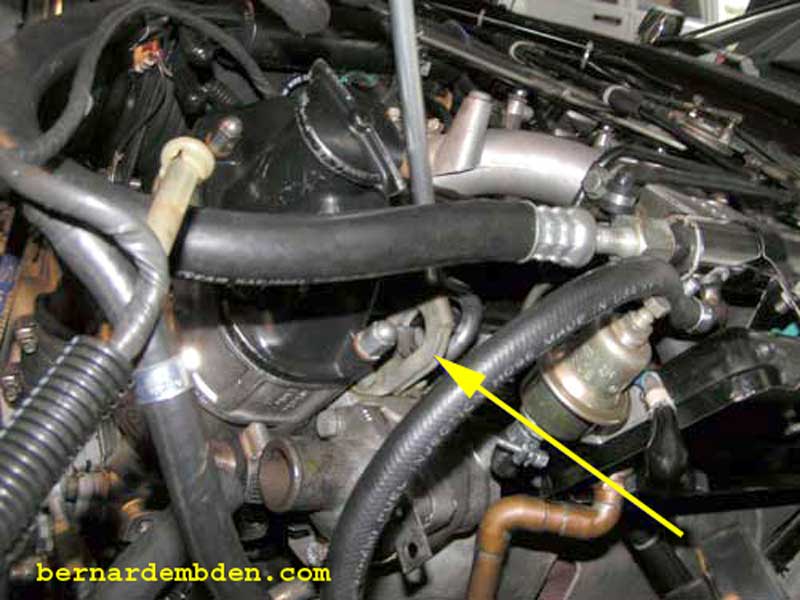
The cut eye-hooks are passed through the right and left engine support brackets just below the cam covers. (yellow arrows photographs below).
I cut two pieces of angle iron the width of both beams and drilled holes to accept the threaded portion of the eye-hooks.

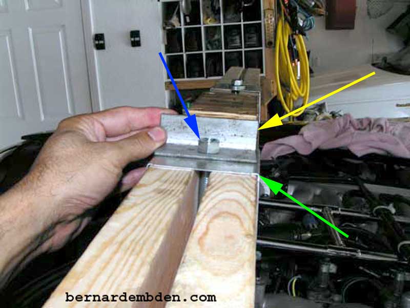
In the photograph below, the 4x4 metal post supports are installed over both beams. (green arrow) These not only help to equalize the load, it ensures that the beams could not move apart as this location. The angle iron (yellow arrow) rests on these metal supports to ensure that the load is equalized across both support beams. The two beam design allows me to insert the threaded portion of the eye- hooks between the wood beams, through the 4x4 metal posts supports and through the angle iron before attaching the nut. (blue arrow).
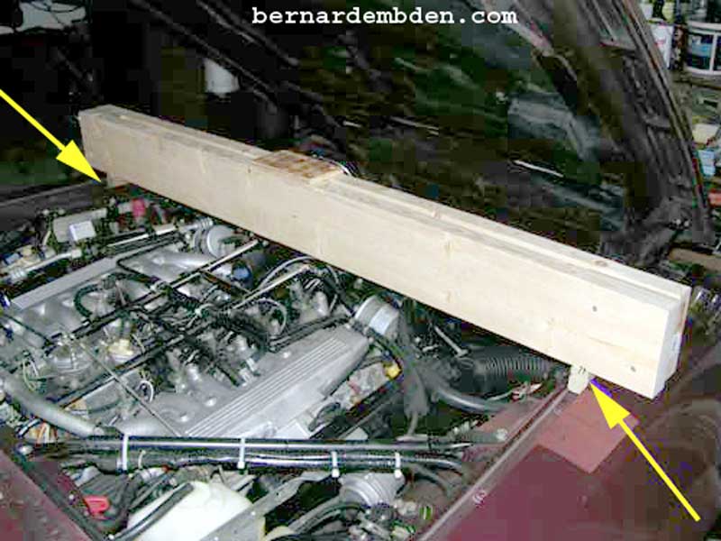
The completed engine support installed on my car for a project: Replacing the gaskets and suspension cradle mounts. The green arrows identify the support "feet" The yellow arrows shows the eye-hooks supporting the engine.
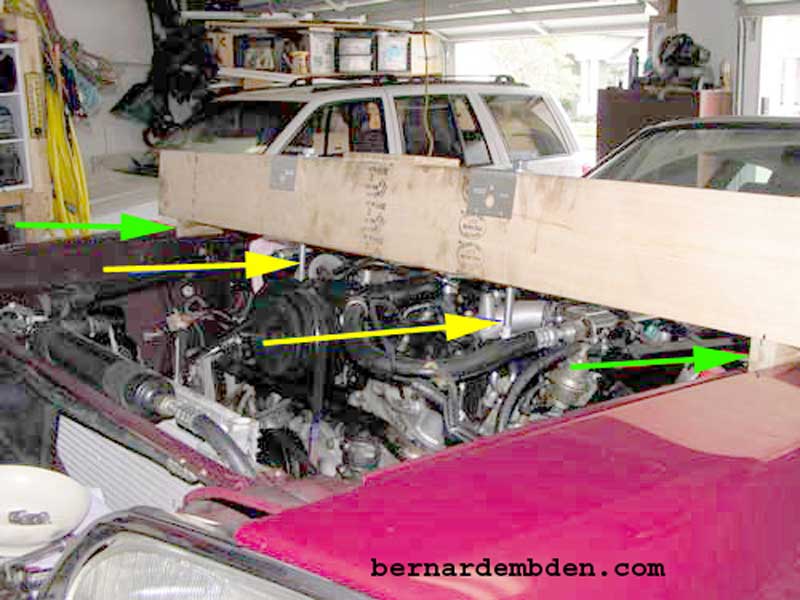
This engine support has been holding up my engine for the last six weeks, (work tends to get in the way) and as the above photograph indicates, with absolutely no problems.
This is not a difficult project. Time, a couple of hours. Cost $20.00 US.
