
The speedometer on my 1978 Jaguar XJ-S had become problematic. Jaguar inexplicitly routed the speedometer cable in such a fashion as to guarantee that the cable will bind at some point in the car's lifetime. Nothing else makes sense. After the right angle drive behind the speedometer died some years ago. I then rerouted the cable to eliminate or decrease the bends along with eliminating that right angle drive. (see appropriate link on this website) Now, the cable was binding in the speedometer housing. It would have to be replaced.
To complicate matters, I was having some difficulty sourcing a new cable and housing. During this process Dennis Cunningham graciously donated to me the dashboard and pulse generator from his 1983 XJ-S parts vehicle.
Note that this modification goes against my number one rule whenever I change anything on my car. That is, make it simpler and more reliable.
Nevertheless, this project would replace a simplistic, mechanical cable driven speedometer, with an electronic speedometer driven by a pulse generator off the right angle gear at the transmission.
The project starts with the removal of the dashboard, old speedometer cable and housing. Remove right angle drives from transmission and speedometer. I was getting slight oil leakage from the transmission's speedometer assembly. This was the opportunity to replace the transmission gear's O-ring. Remove the holding screw and withdraw the assembly (photograph below).
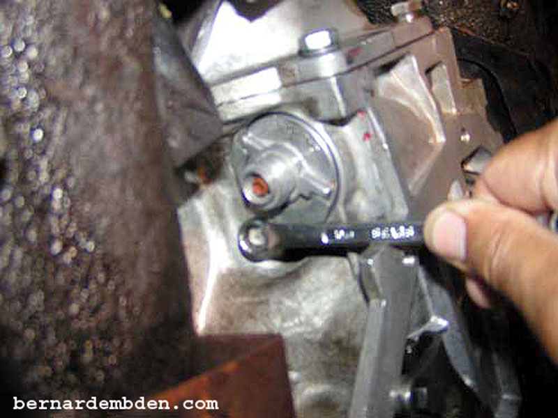
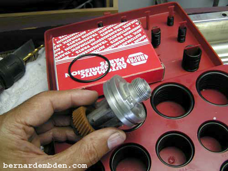
If the speedometer gear needs replacement now is the time. I replaced the large O-ring. This is a standard NAPA part for the TH-400 transmission. I also made a 1/2-inch hole below the radio on the left side of the transmission tunnel to run the pulse generator wires. Make the hole close enough to the transmission connection so the pulse generator's plug will be inside the car when the project is completed.
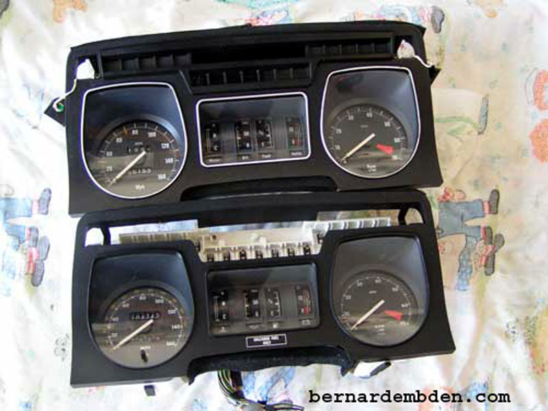
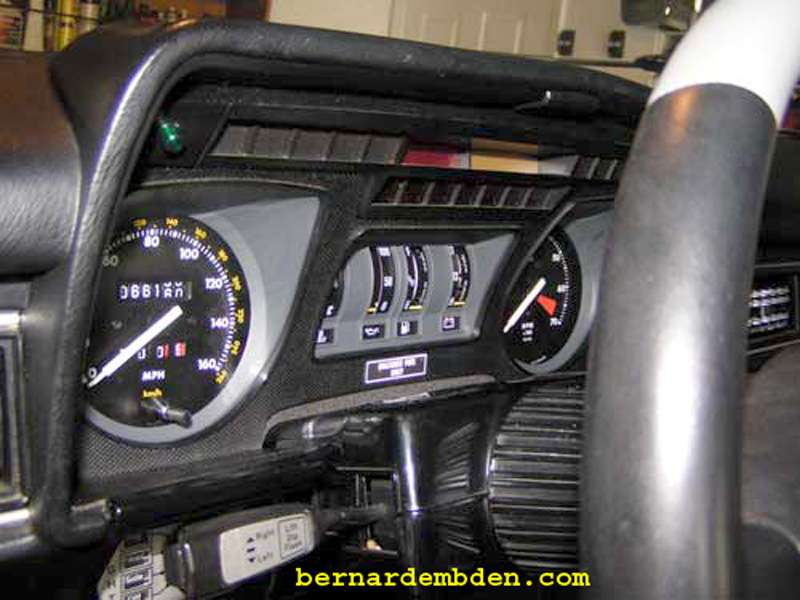
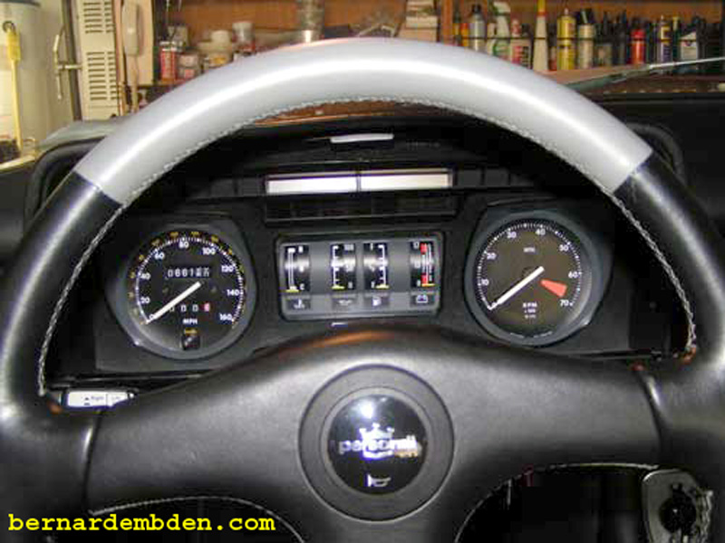
(Photograph below) Examination of the fronts of my original 1978 (top photograph) and the 1983 (bottom photograph) dashboards reveal few visual differences. On the 1983 speedometer, the trip counters and mileage indicators are reversed, top to bottom. The letters and numbers on the 1983 speedometer and tachometer are also slightly smaller.
The differences are more apparent when viewed from the rear. The 1983 dashboard (bottom photograph) is extended to accommodate the electronic speedometers logic board. There are also four additional contacts specifically for the speedometer.
The yellow arrow identifies a new, additional connection on the flexible circuit board. This connection goes to the bottom lug on the speedometer, identified by the light blue arrow. This is the connection that receives input from the signal side of the pulse generator.
The red arrow identifies the 12 volt speedometer connection.
The green arrow identifies the speedometer's ground connection.
![]()
To complete this project you will need the new speedometer housing (dashboard) along with the flexible circuit board. While it is possible to accomplish this with only the electronic speedometer, the job becomes significantly more difficult.
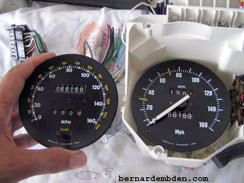
Remove electronic speedometer. Examination of the old and new speedometer reveals a significant difference in mileage. Since I was not about to install a speedometer with the incorrect mileage, I took apart the electronic speedometer and set the mileage to the exact number as my original. I have specifically not detailed how this was done. This entire website is about working on and improving Jaguars, not reversing speedometer mileages (smile).
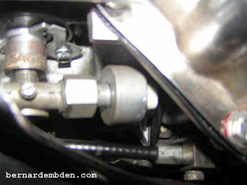
(Photographs below) Install pulse generator. This device attaches to the right angle drive at the transmission.
![]()
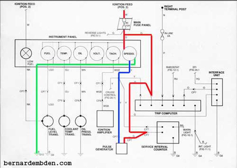
Below is a wiring diagram of the installation. The red line indicate 12 volts from the switched on number 2 position of the ignition switch. The blue line is the pulse signal from the pulse generator attached to the right angle drive at the transmission. This connects to the new contact on the flexible circuit board. The green line is ground.
The new flexible circuit board feeds the correct voltage and ground to the speedometer connections identified by red and green arrows. (prior photograph) No modifications are necessary there. The modifications necessary will apply 12 volts from the switched on number 2 position of the ignition switch to the positive (+) connection of the pulse generator, and connect the pulse signals from the other connection of the pulse generator to the new (vacant) connection in the flexible circuit board.
The first step was to activate the empty slot in the existing wiring harness plug. I sourced a connection from a spare plug, soldered a wire to it and inserted it in my existing harness connector (yellow arrow photographs below). This new connection connects the bottom connection of the electronic speedometer to the signal wire from the pulse generator.
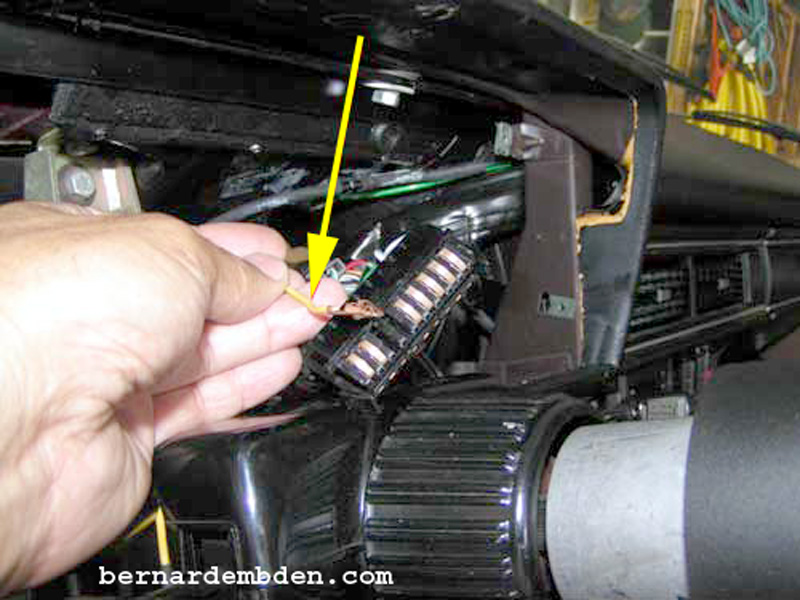
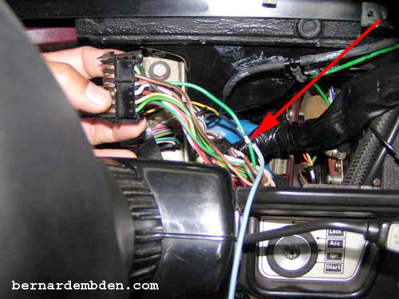
The next step was to provide 12 volts "ignition on" switched power to the positive (+) connection of the pulse generator. I identified the wire I needed (number 3 position on the small harness plug) and soldered a bridged connection. (red arrow photograph below).
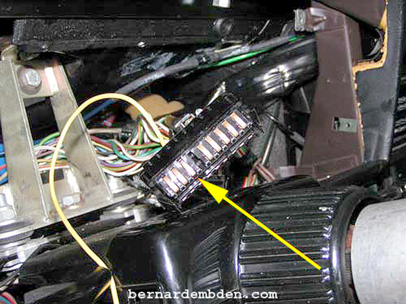
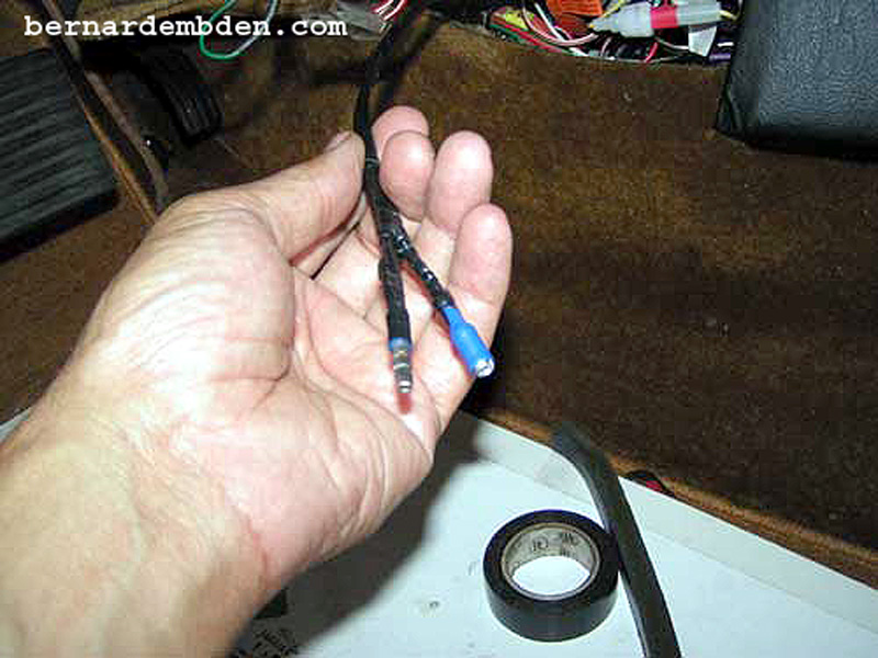
These are the two wires that will be routed to the pulse generator. Note that you could just attach these wires to the appropriate connections on the back of the speedometer, but it would not look right.
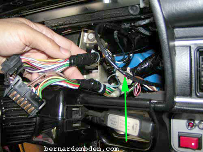
Tape and wrap all wires behind the dashboard. Note taped wires that will go to the pulse generator (green arrow)
Photograph below. I was unable to source a suitable plug that would connect to the pulse generator. I soldered "bullet" type male and female connectors and connected them to the pulse generator plug. Make sure the positive (+) marking on the pulse generator plug gets connected to the 12 volts switched power from the wiring harness. You can test this by connecting the pulse generator temporally inside the car and turning it by hand.
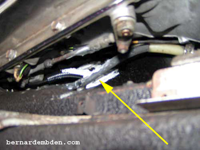
I protected the wires as they passed through the transmission tunnel with wiring loom and sealed the opening with silicone caulk. (yellow arrow photograph below).
Install new dashboard. Although not functionally necessary, I used the new tachometer to match the new speedometer.
Project complete.
