
The original radio in the 1978 Jaguar XJ-S is a two post design that was the standard configuration when this car was manufactured.
This design is no longer available. Radios are either designed specifically for a particular car model, or to fit inside a "DIN" opening.
DIN is an acronym for "Deutsches Institut für Normung", the German Institute for Standardization; similar to the American National Standards Institute (ANSI).
The vast majority of aftermarket radios are designed to fit into DIN openings. The objective of this project was to install an aftermarket radio, designed for a DIN opening, into my 1978 Jaguar XJ-S.
Installing a radio in a DIN opening is not difficult. You could just butcher a hole in the dashboard and stick it in. Installing the radio so it looks as if the car came that way requires effort and attention to detail.
In choosing a new radio, in addition to the standard stuff, I wanted it meet the following criteria:
CD capability
A proper volume control knob
Automatic antenna activation
MP3 capability
USB capability
Finally, the design must fit in and complement the existing radio fascia and location.
The radio I chose is manufactured by Pyle.
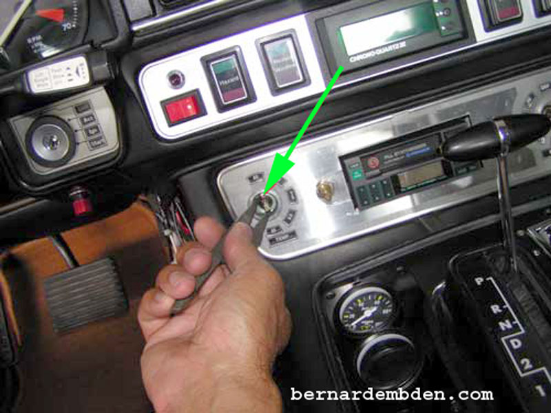
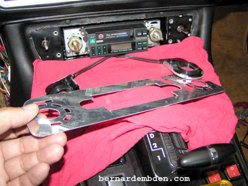
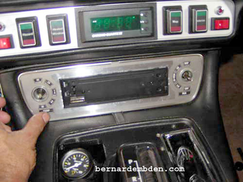
The process starts by removing the radio and HVAC control knobs.
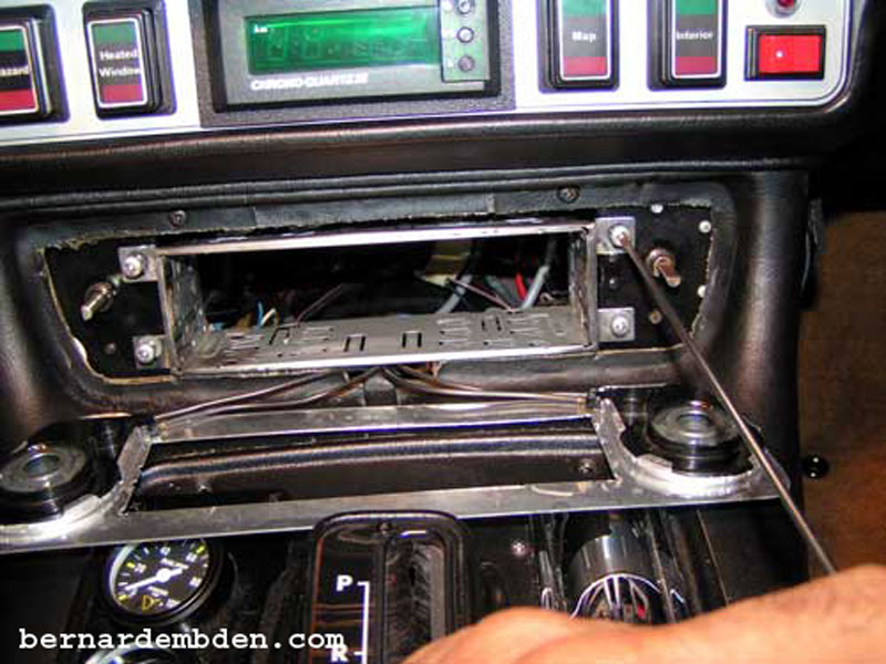
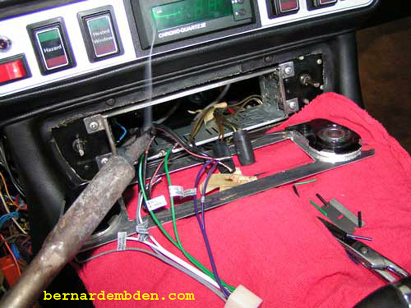
I used a pair of snap-ring pliers to remove the radio fascia mounting screws. (green arrow photographed below).
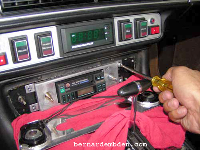
The radio is attached to a front support, which is bolted below the dashboard with four Phillips head screws. (photographed below). Note that this is not the original Jaguar radio. I replaced the radio many years ago when I installed rear speakers. (That radio did not require significant modifications).
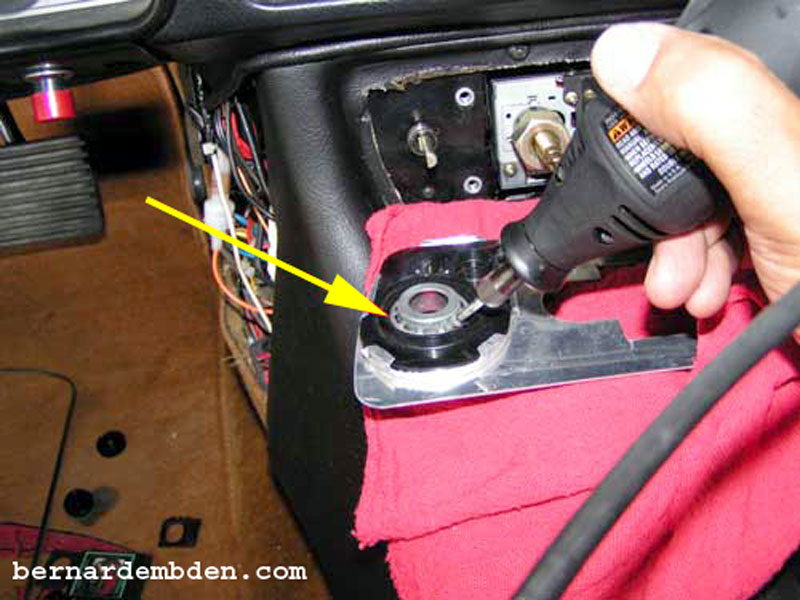
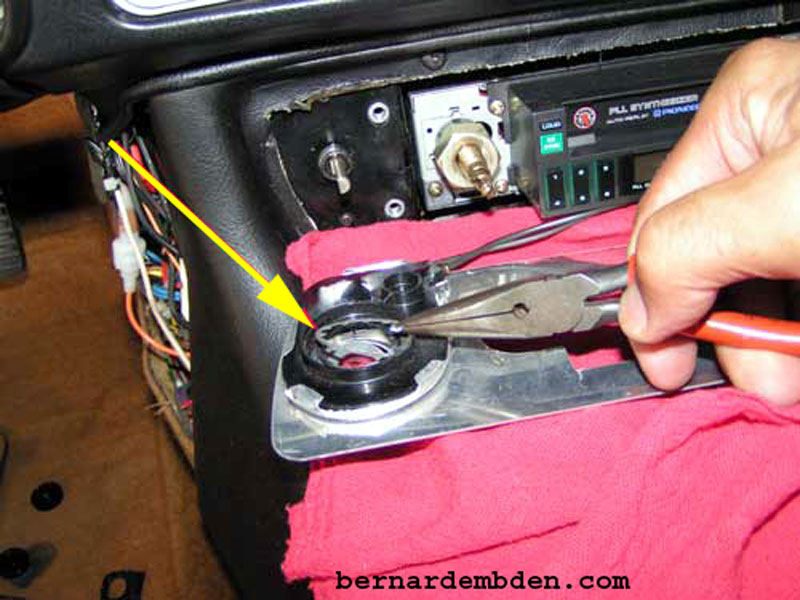
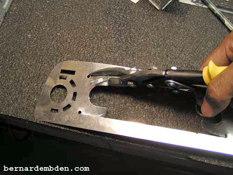
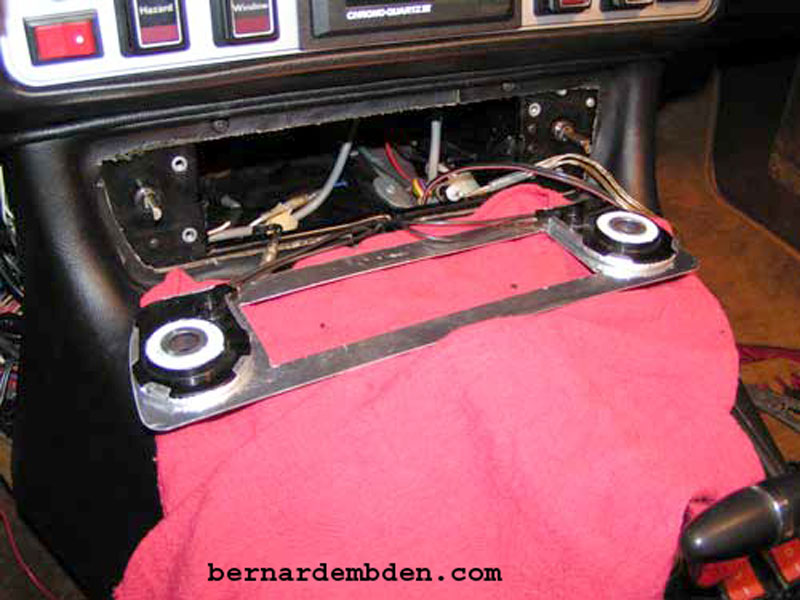
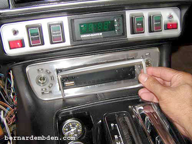
Installing the new radio will require removing and modifying the original radio fascia. Before removing the fascia, the HVAC control assemblies, along with the fiber optic cables, will have to be detached. They are secured to the fascia mounting rings with two star tabbed unidirectional washers. Prying them off would damage the plastic HVAC assemblies. I used a dermal tool to cut the retaining washers prior to removing them. (yellow arrows photographs below).
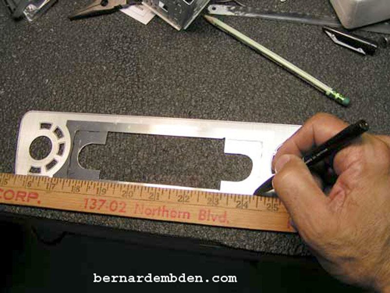
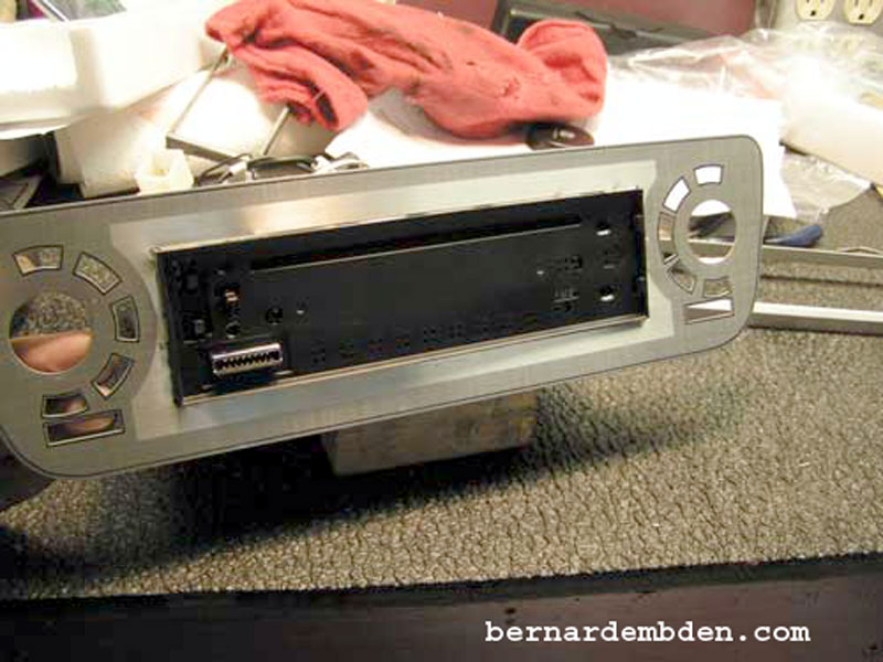
(Photograph below) Using the DIN mounting surround housing that came with the new radio as a guide, I marked the DIN opening in the center of the radio fascia.
This operation is critical to quality of the finished project. The opening must be in the center, equidistant from all sides.
(Photographs below) Drill four small holes at the corners of the marked opening and, using a tin snip, carefully cut out the opening.
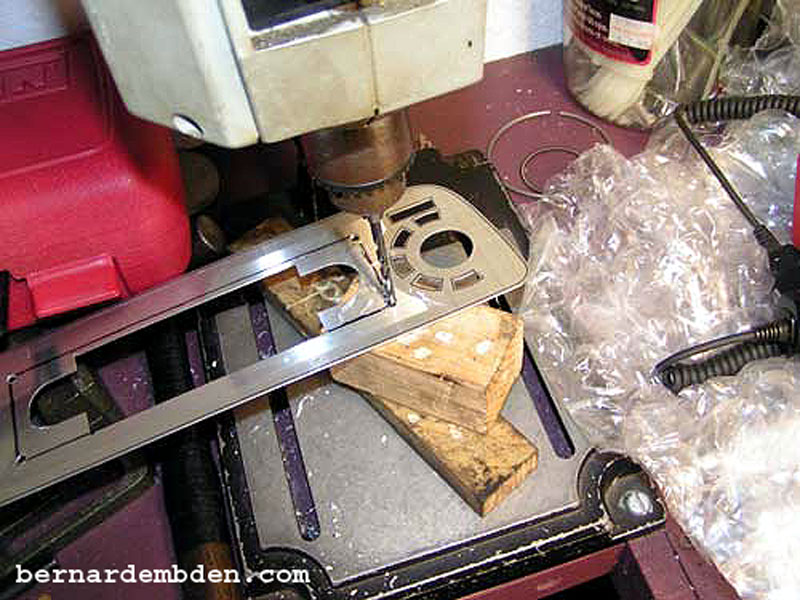
Use a flat file if necessary to smooth the opening to closely fit over the outside of the radio. Tolerances should be tight and uniform. Take your time. There is not much room for error on this.
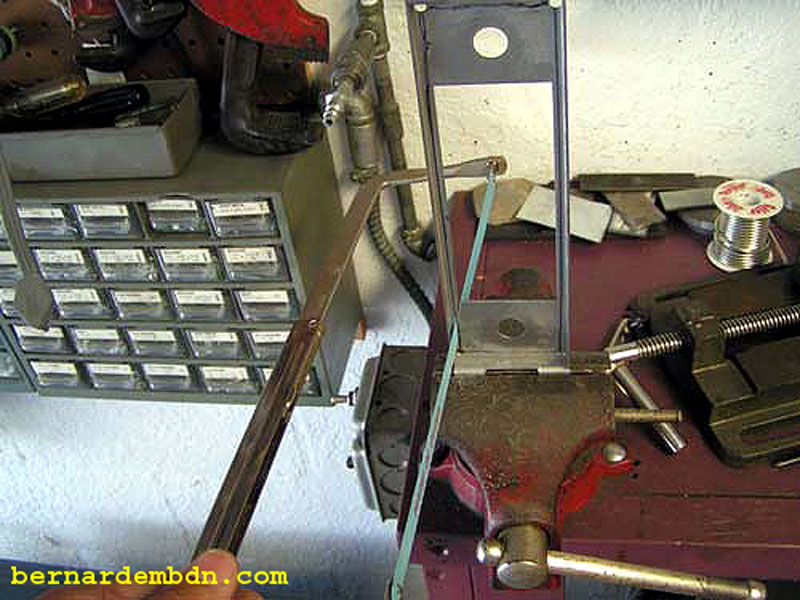
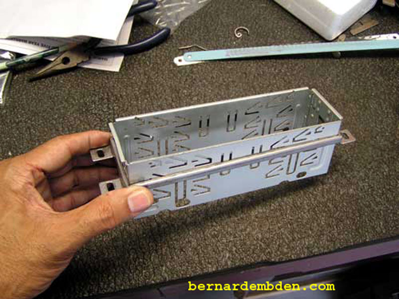
In the photographs below, using the DIN mounting surround that came with the new radio as a template, mark the original radio front support. Using a hacksaw, cut out the front support opening.
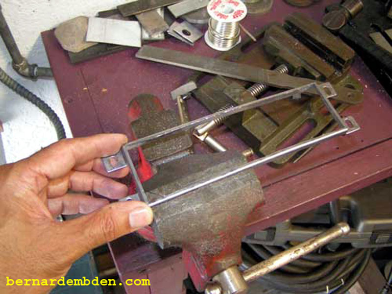
As the photograph below illustrates, the front radio support should now fit snugly around the DIN mounting surround housing.
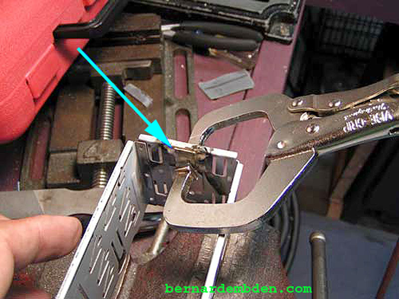
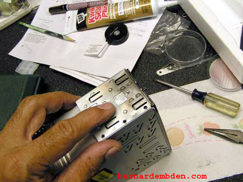
The radio has two spring loaded side tabs that fit in corresponding slots in the DIN mounting surround. These are designed to locate the radio securely in the correct position within the DIN housing. The methodology for mounting the radio will preclude access to these tabs, therefore they will have to be modified. This modification will allow removal of the radio through the front fascia. Fabricate two pieces of stock metal to cover their openings and braze then to the DIN surround. (light blue arrows photographs below).
The photograph below show the modified DIN surround. The blue arrow shows the metal brazed to bridge the slot opening. The green arrow identified the spring loaded side tab.
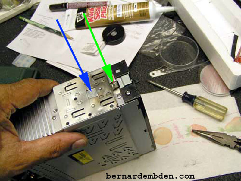
With the DIN surround installed around the radio the spring loaded side tabs hold the radio securely. The housing modification allows the radio to disengage from the side tabs without manually pushing the tabs in, allowing the radio to be withdrawn from the front of the surround housing.
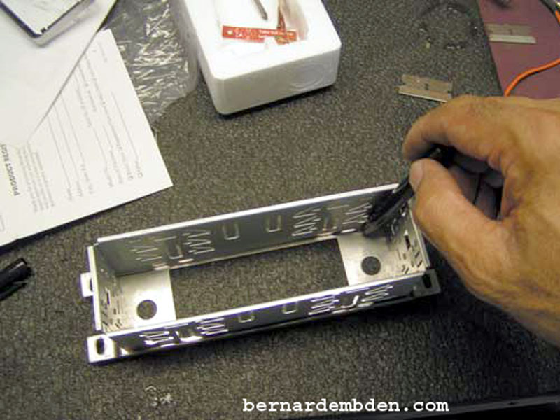
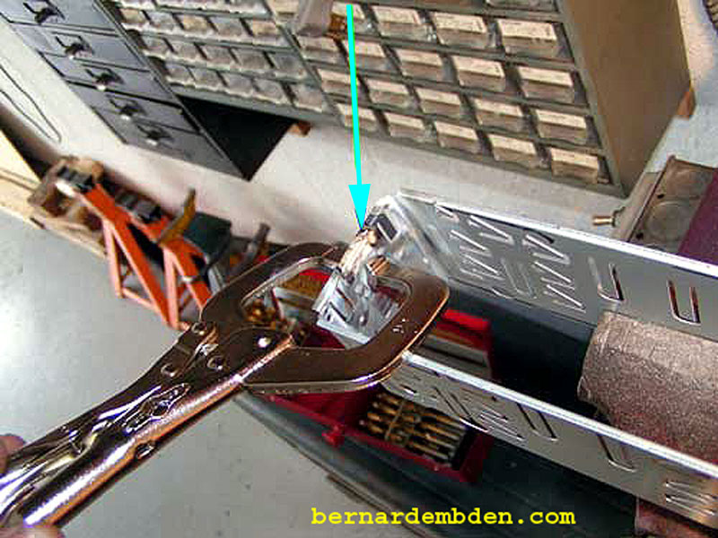
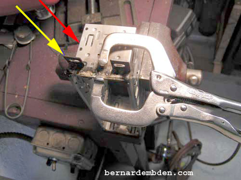
With the DIN surround and front radio support panel suitably modified, install DIN surround (red arrow photograph below) inside the front support (yellow arrow). I used a specialized vice grip to hold the front support flush with the front of the DIN surround while I brazed the modified front support to the housing.
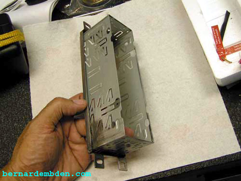
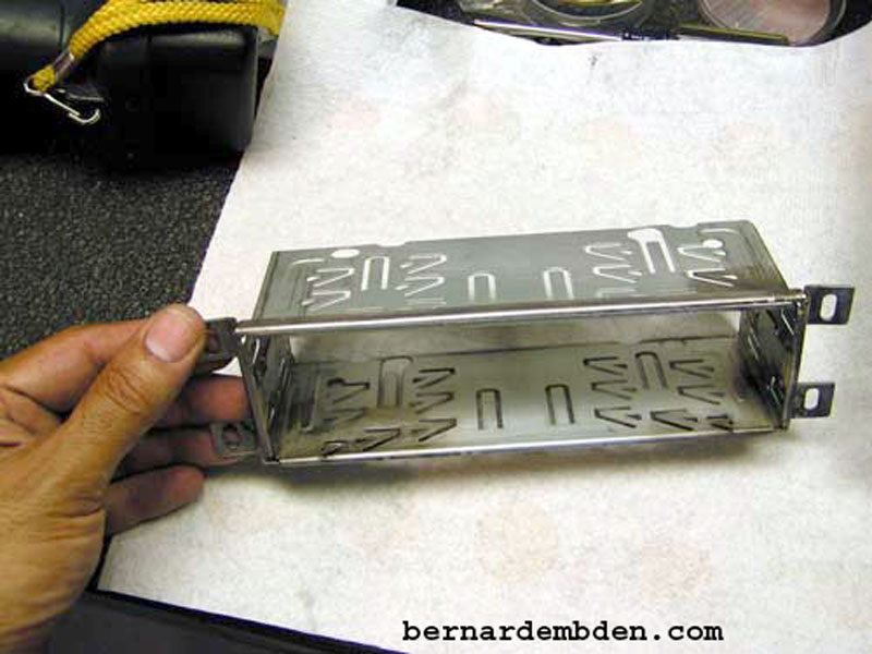
The finished modified radio support housing and front radio panel should look like photographs below.
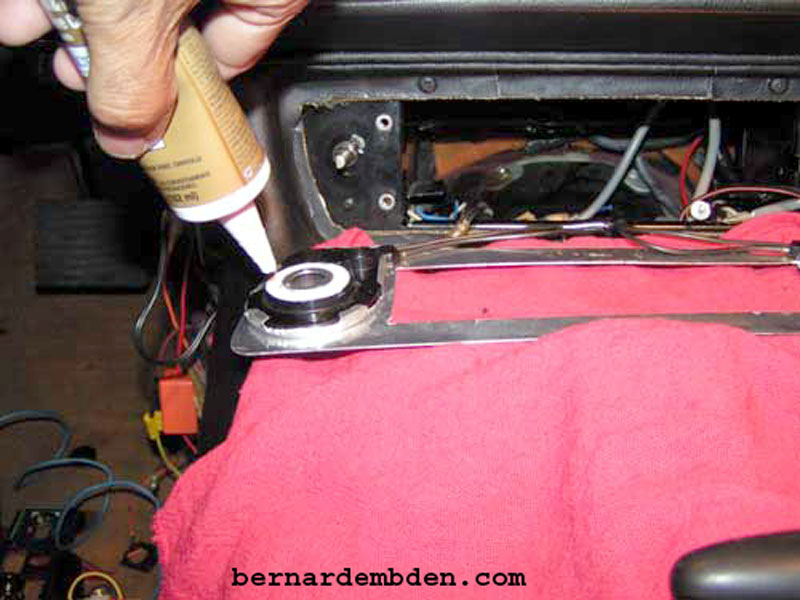
Reinstall the HVAC control assemblies to the radio fascia. I reused the cut star tabbed unidirectional washers to initially hold the assemblies in position while using silicone caulk to secure them.
Install modified front radio surround housing support with the four original Phillips screws. The support holes are slotted to provide some mounting adjustments.
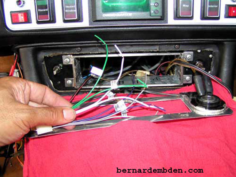
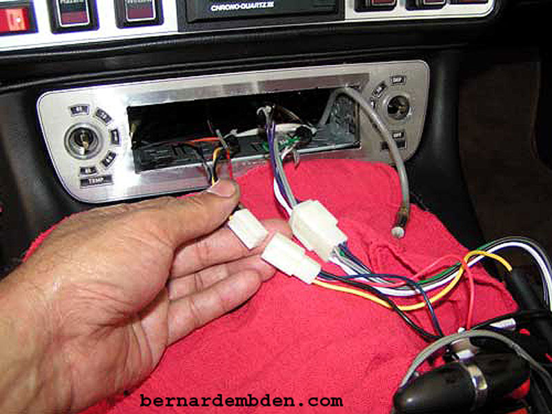
All aftermarket radios should come with labeled wires. Connect the appropriate speaker, power, antenna and ground wires to the supplied, radio specific, plugs.
This radio required a constant 12 volt, 15 Amp power supply. (blue arrow photograph below).
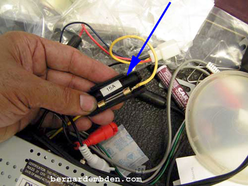
Whenever any voltage requirement is this high it's never a good idea to bridge off any existing wire. Run a dedicated wire. I sourced 12 volts directly from the bus bar at the engine firewall (green arrow photograph below). I discarded the radio provided inline 15-amp fuse. I installed fuse holder with a 15 Amp fuse close the bus bar connection. (yellow arrow).

Solder and heat shrink all speaker, ground and power connections.
Install radio front fascia. Feed antenna, speaker and power wires through front fascia and connect to radio.
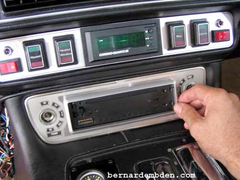
Slide radio through front fascia and DIN surround housing until the radio flange (yellow arrows photographs below) is snug up against the front fascia.
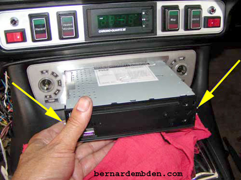
Radio bezel snaps into slots in the DIN housing.
Detachable radio front snaps into radio.
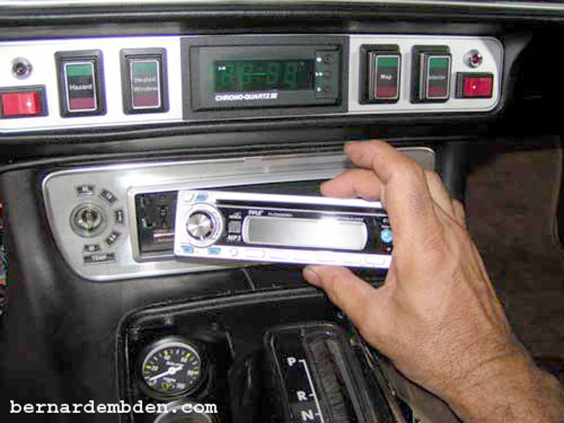
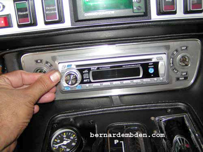
Install HVAC control knobs.
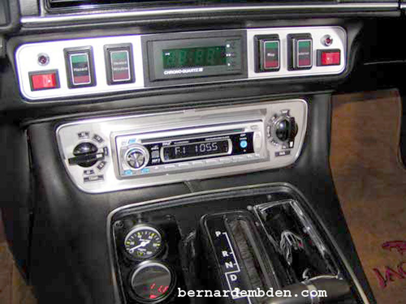
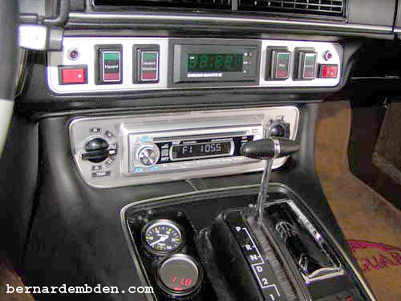
Project complete.
