
The location of the power steering cooler has always concerned me. It seemed illogical to position the cooler inches away from the exhaust manifold enclosed in an engine compartment that is legendary for its heat. I believe it's not unreasonable to assume that in normal driving conditions the cooler functions more as a heat collector than a cooler, thus defeating the very purpose for which it was designed.
This project was to relocate the cooler to an optimum location, in front of the radiator directly in the airflow.
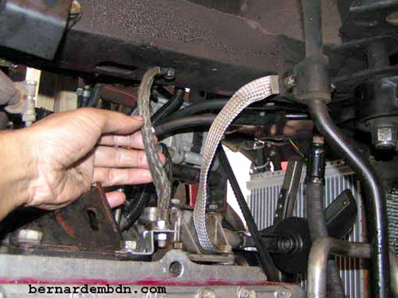
The cooler is located on the left side of the engine bay below the power steering pump. Congesting this location are hoses from the power steering pump and rack, the left engine motor mount and the ground strap from the chassis to the engine block.
The ground strap has the potential to chafe the power steering hoses, so I decided to first relocate the ground strap to the other side of the engine. I also added an additional ground strap for good measure. (Photograph below)
In the following photographs the radiator and fans have been removed. Although not absolutely necessary, it does make this modification easier.
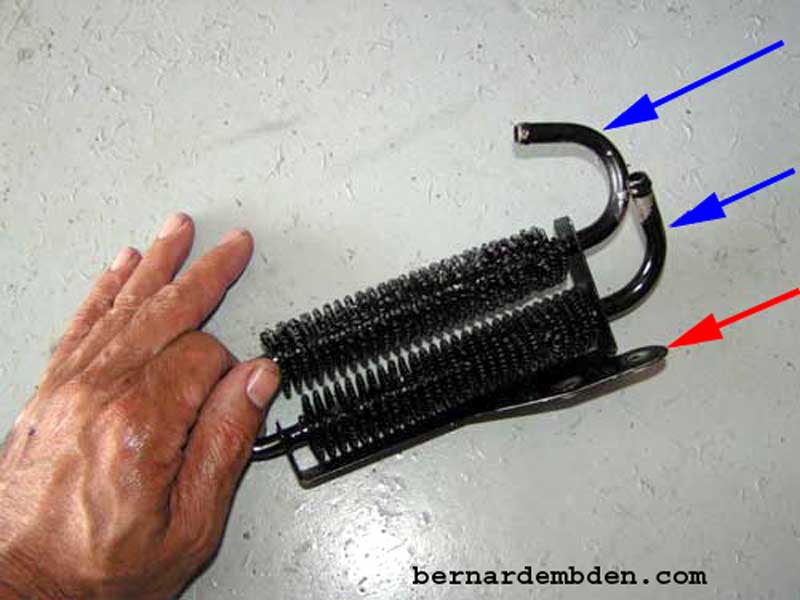
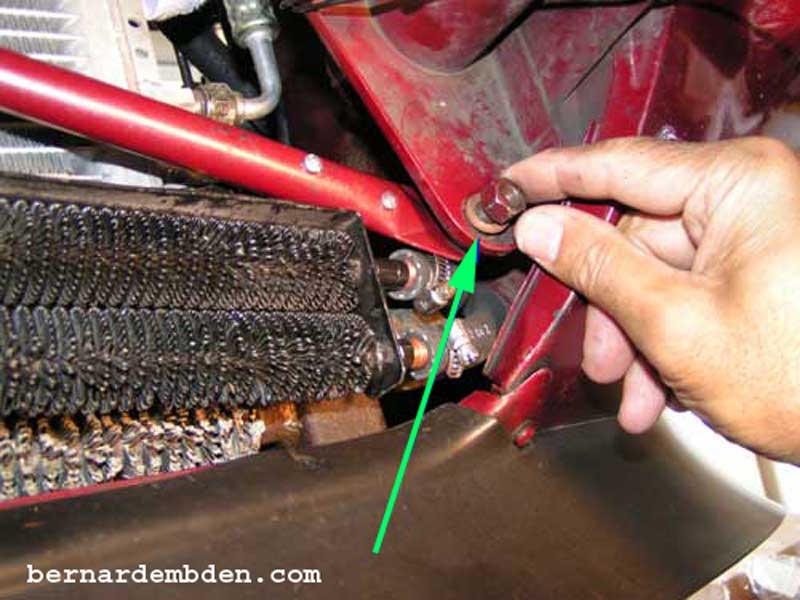
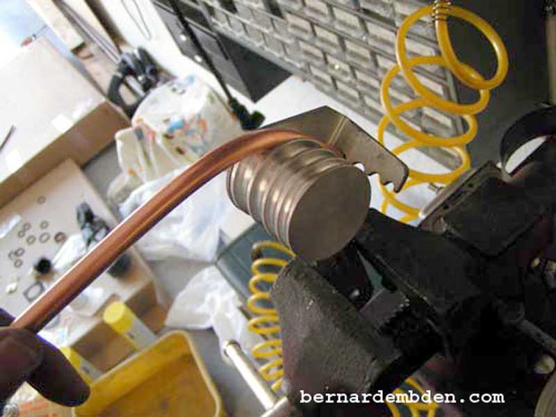
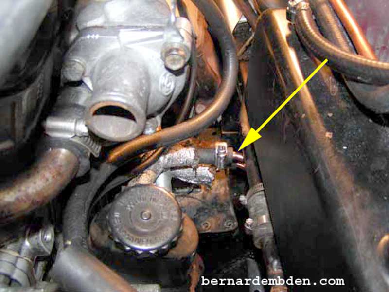
The power steering cooler is attached to the left engine motor mount bracket with two bolts. Remove bolts and disconnect the inlet and outlet hoses. In the photograph below, note the angle on the cooler's inlet and outlet pipes (blue arrows). These, along with the mounting bracket (red arrow) will have to be modified.
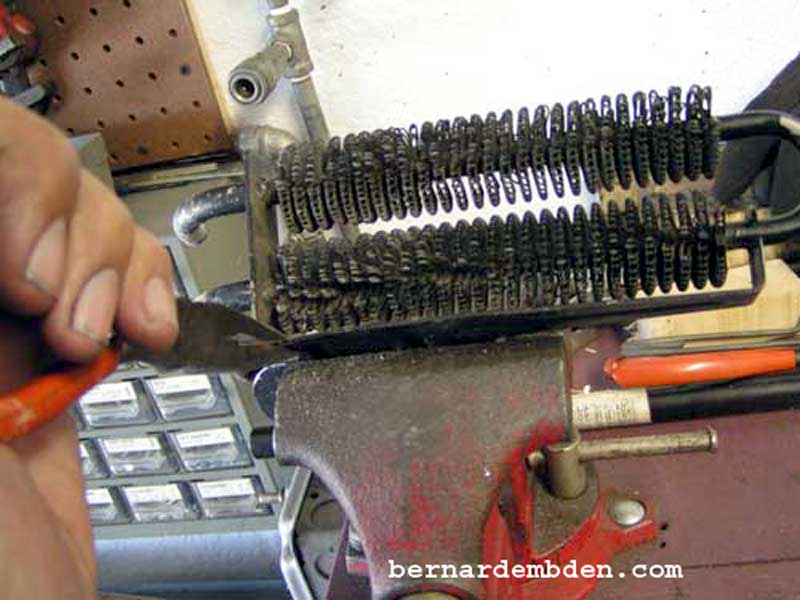
Using a vice to secure the cooler I bent the mounting bracket 90 degrees. (made it straight). Use care as the bracket is thinly soldered to the cooler pipes. In addition, it has two ribs that provides strength to the bracket metal. I drilled two holes along these ribs to facilitate bending of the material.
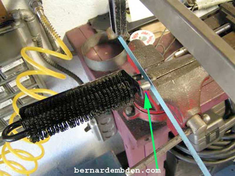
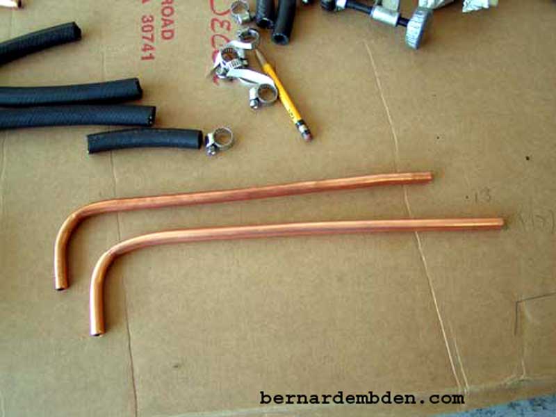
The power steering cooler's inlet and outlet pipe bends would not allow mounting in the location I wanted. I needed to cut each pipe in two locations. The first cut saved the nipple ends of the pipes. The second cut eliminated the bends. (green arrow photograph below).
It's important to save and re-use the pipe nipples as these ridges help secure the hose over the pipe. Without them the hose could work its way off the pipe. I used 3/8-inch sweat copper unions to solder the cut nipples to the shortened pipes. (green arrows photograph below).
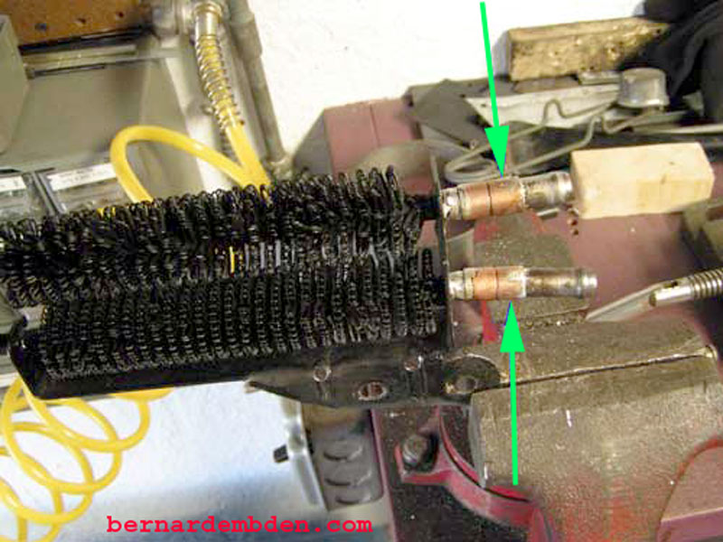
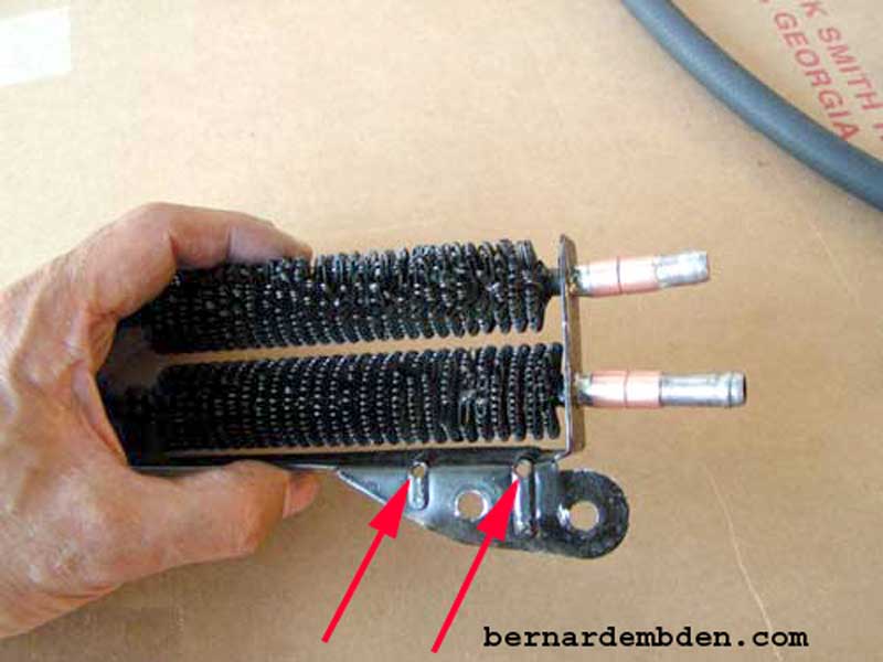
Clean excess solder from both connections. In the photograph below note bracket bend 90 degrees with two holes drilled to facilitate bending. (red arrows)
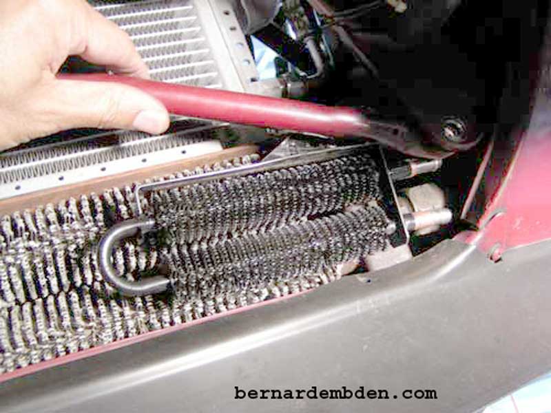
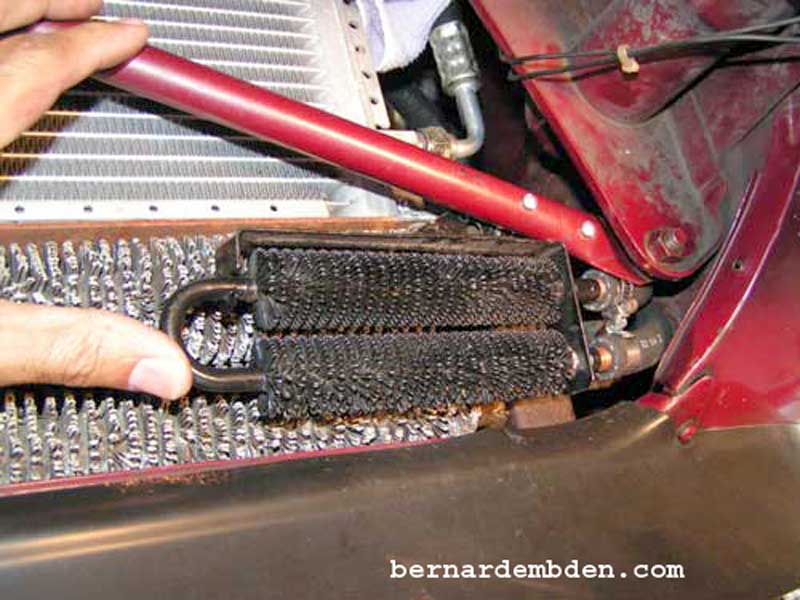
The XJ-S V-12 cooling system is designed with very little reserve. For this reason I intended to install the modified cooler between the oil cooler fins and the lower radiator grill, keeping it out of the primary radiator airflow. In the photograph below, the initial test fitting at the preferred location indicated that the modified cooler (bent bracket and shortened pipe nipples) was now ready to be mounted.
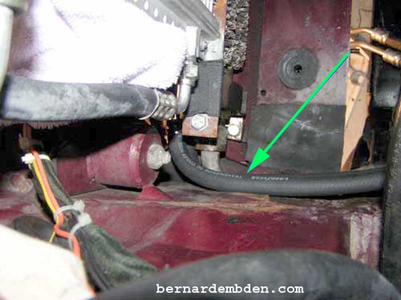
You will need 36 inches of 3/8 rubber hose specifically designed for transmission fluid. I cut two 12-inch lengths and installed them on the cooler nipples. Once the proper angle was determined I drilled two holes through the radiator opening diagonal brace (green arrows photograph below) prior to mounting the cooler.
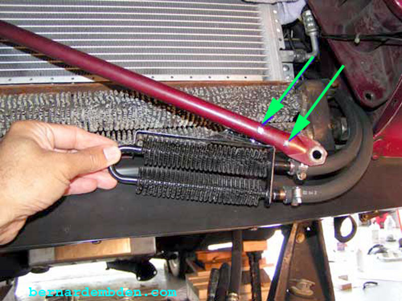
With the cooler mounted, I reversed the diagonal braces lower bolt to provide clearance with the cooler's upper hose connection. (green arrow photograph below)
In the photograph below, it is critical that the cooler hoses lay flush against the radiator opening (green arrow) Once the radiator in installed, the space between the radiator and chassis frame becomes extremely limited.
In the event that the cooler hoses does not provide enough clearance for the radiator an option is to replace the hoses with copper pipe.
You could run the hoses directly back to the power steering pump and steering rack and it would work. However it would look better with copper pipes. I purchased a roll of 3/8 inch copper tubing from Home Depot.
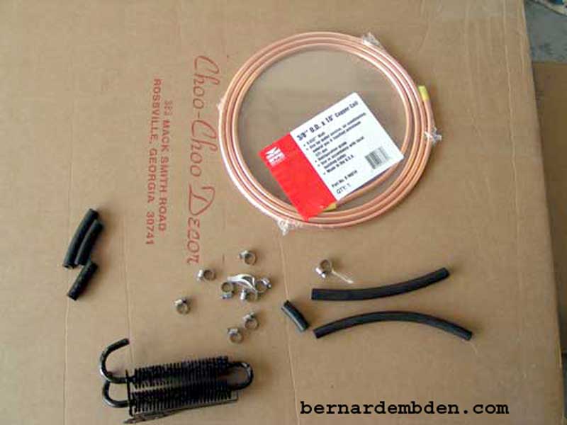
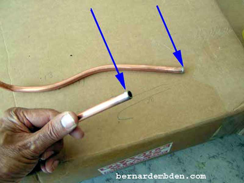
I cut two lengths of pipe each approximately 12 and 14 inches. Using a tube bender I bent each pipe approximately three inches from one end.
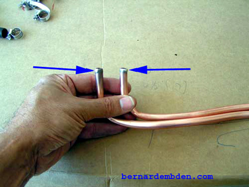
In order to make sure the hoses stayed on the copper pipes I soldered nipples on the end of the pipes. Clean and flux the very end of the pipe. Solder with low heat just enough to form a bead.
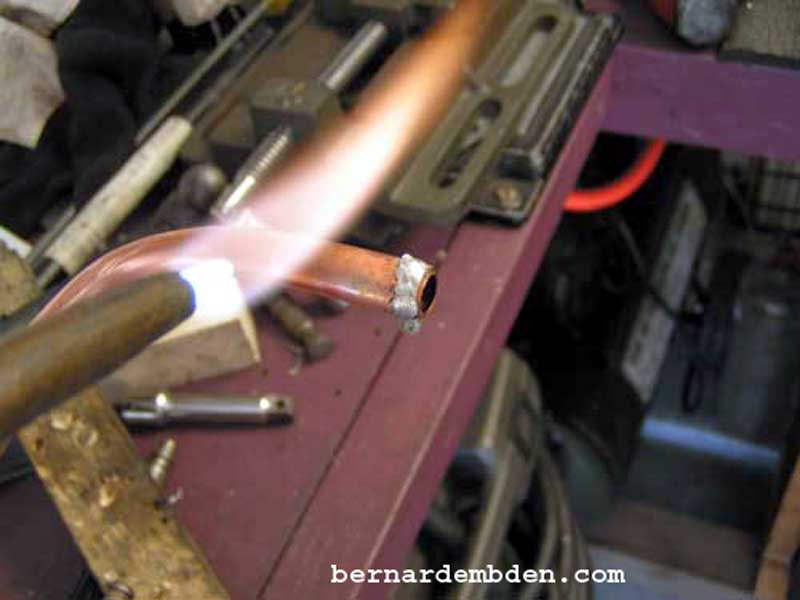
File and sand the soldered copper pipe end until the nipples are created (blue arrows photographs below).
I used aluminum clamps with rubber coverings to secure the copper pipes. I drilled two holes in the frame (blue arrow) and secured the front clamps with self-tapping screws.

In the photograph below, I used the existing hole that previously attached the ground strap to secure the rear aluminum clamps to the copper pipes.
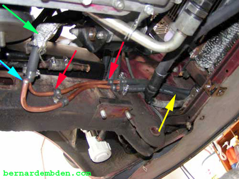
(red arrows) Rubber insulated clamps.
(blue arrow) Inlet from the power steering rack.
(green arrow) Connection to the power steering pump.
(yellow arrow) Hoses from relocated power steering cooler.
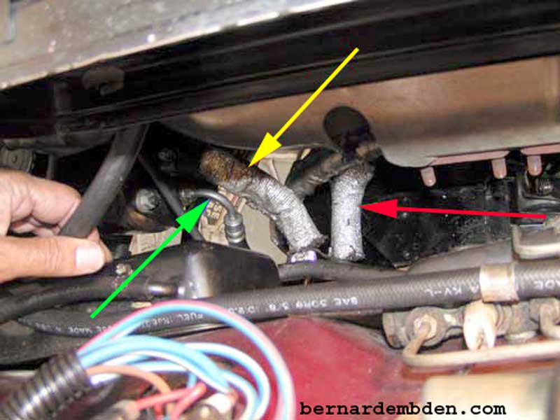
Make sure the heat sleeves are installed over the hoses when the final connections are made. Pictured below are the connections to the power steering rack, pump and cooler.
(green arrow) Power steering pump high-pressure line to steering rack.
(yellow arrow) Power steering pump low-pressure return line from relocated cooler.
(red arrow) Low pressure return line from steering rack to relocated cooler.
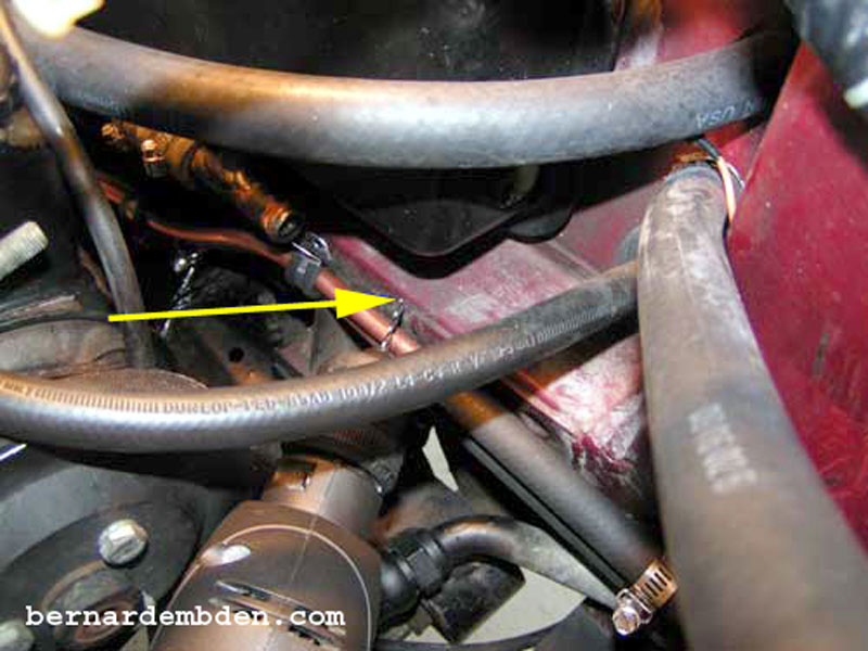
Connections from the steering rack and power steering pump to the cooler copper lines. (yellow arrow photograph below).
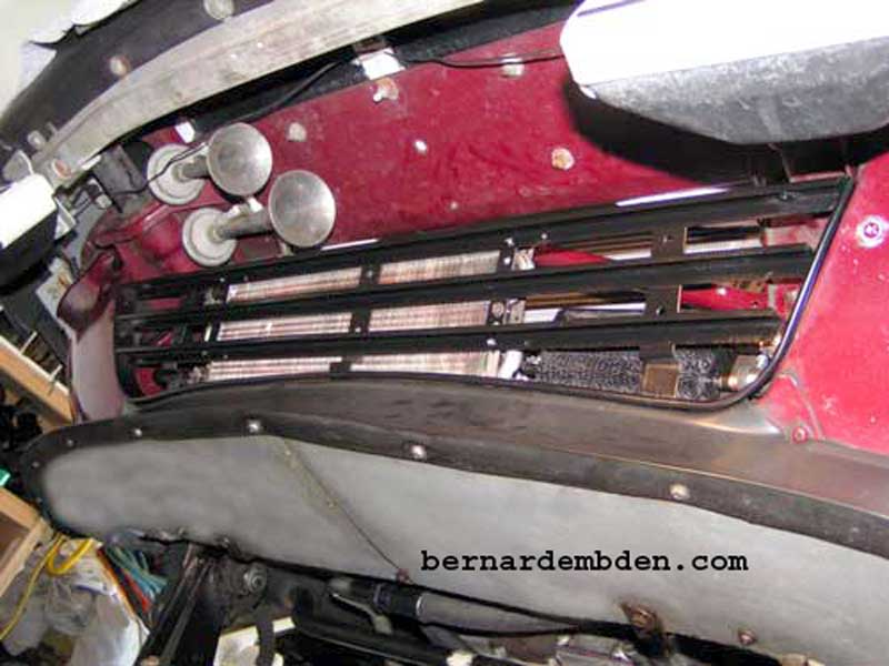
As detailed elsewhere on my website, I have an external transmission cooler installed on the lower front grill. This had to be repositioned slightly to make room for the relocated power steering cooler. (photograph below).
![]()
Reinstall lower grill.
Project complete. The cooler is now positioned where it can function as designed, keeping the power steering fluid cool.
