
The 1978 Jaguar XJS's main fuse box has 12 barrel type glass fuses. The objective is to replace this 12 unit fuse box with a fuse panel that has a minimum capacity of 14 modern ATO/ATC fuses.
A second objective is that no wires would be lengthened, therefore it was imperative that the new panel fit in essentially the same location as the original fuse box.
And of course it needs to look good.
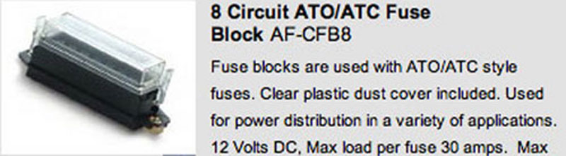
To accomplish this two fuse blocks were needed, each having the capacity to carry eight fuses each. Personal preferences, along with existing space limitations necessitated that all wiring must enter and exit from the bottom of the fuse blocks.
The fuse blocks (photographed below) were sourced from www.wiringproducts.com. They carry a maximum rating of 30 amps per fuse. Note that these are Automotive Glass Cartridge (AGC) ratings. These fuse ratings differ significantly from the original Jaguar fuses designed for British Standard wiring. This is covered in detail in another link of this website that covers replacement of the fuse box.
The original fuse box is bolted to a mounting plate that is attached to the left side blower motor and is accessed by removing the left side under scuttle.
Remove the old fuse box, associated flashers and the top bracket that the ignitions relay is mounted to.
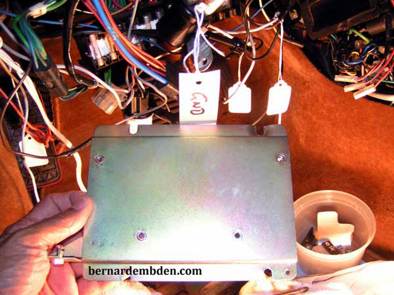
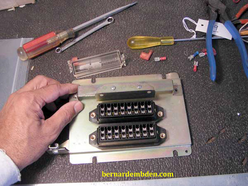
Remove fuse box mounting plate. (photographed below) This will be the starting point for this project.
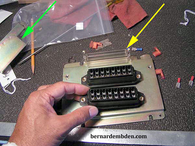
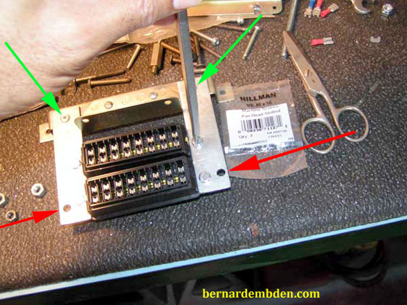
(Photograph below) Position the new fuse boxes on the mounting plate. The location is important. No wire will be lengthened; therefore the two new fuse boxes must be in approximately the same location as the original fuse box. Note the top relay-mounting bracket (green arrow) and fuse block clear plastic cover. (yellow arrow).
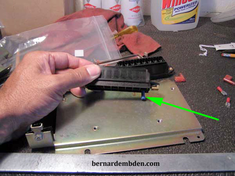
Two issues became apparent. The top fuse box intruded in the location of the top relay bracket and the fuse boxes needed to be mounted approximately 1/2 inch above the mounting plate to be level with the relay mounting top bracket and allow underneath attachments of wire blade connectors. (green arrow photograph below).
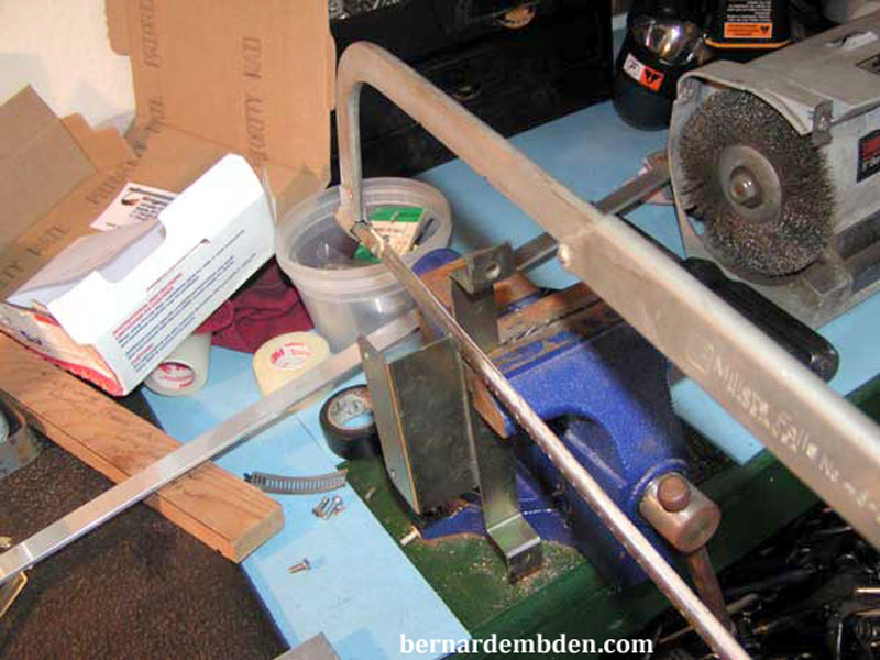
Using a hacksaw, cut the relay mounting flange off the top bracket as detailed in the photograph below.
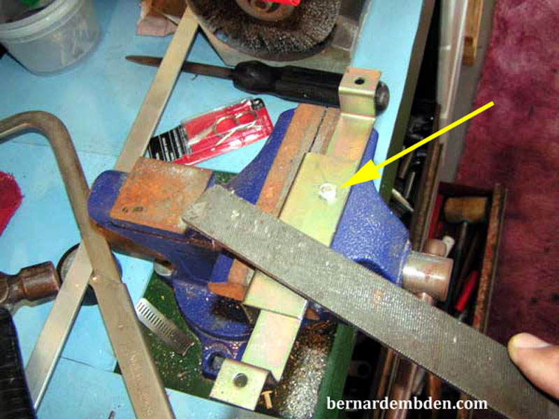
Bolt or rivet the cut off relay flange back on top of the mounting bracket. The objective is to move the relay mounting flange closer to the mounting bracket. This will create the room necessary to mount the top fuse box. The top bracket also serves as a wire retainer, as all the wires to the fuse panel are routed behind this bracket. To ensure that these wires will not be chafed, file the rivets or mounting bolts smooth. (yellow arrow photograph below).
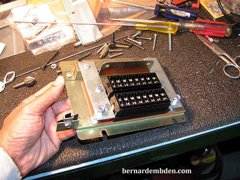
Photographed below is the final layout with the modified top bracket in its proper mounting location, along with the two new fuse boxes.
The objective is to suspend the new fuse boxes 1/2 inch above the mounting plate. Cut two lengths of metal stock (yellow arrows photograph below) which will be the fuse boxes side supports.
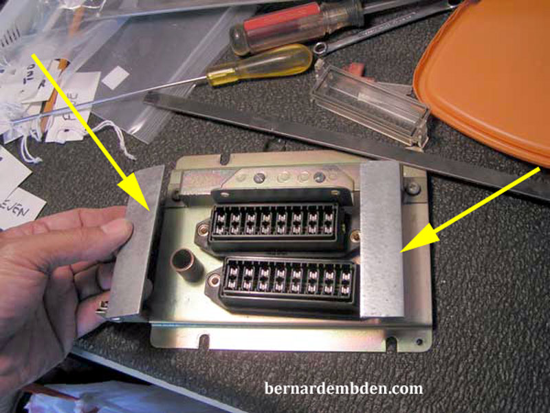
(Photograph below) Offer up the fuse boxes to the side supports. Mark the mountings holes and drill the side supports to allow the fuse boxes to be mounted underneath the metal stock. Using four M5 80x10 metric bolts attach the fuse boxes to the side supports.
Rivet the supports to the modified top bracket. (green arrows). Drill two additional holes in the side supports (red arrows) necessary for stand offs to support the bottom of the assembly at the required height.
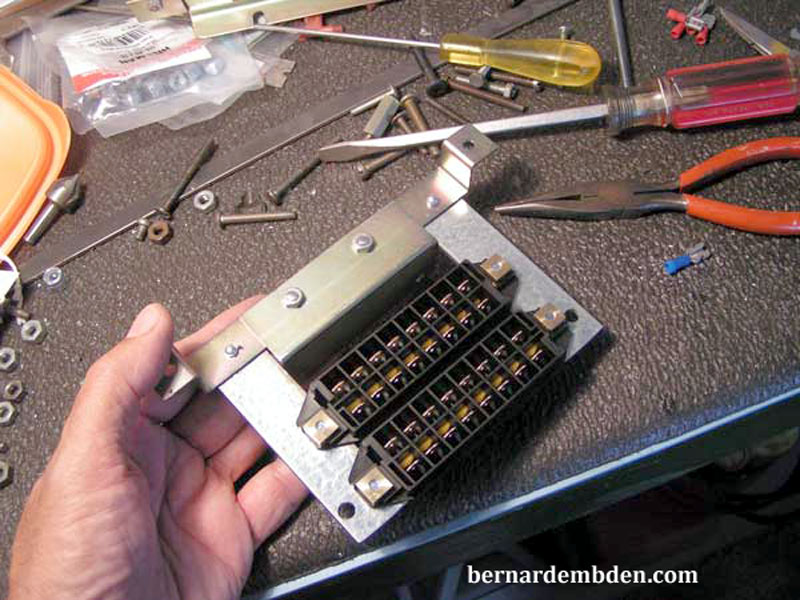
The completed fuse box assemblies (bottom view) are photographed below.
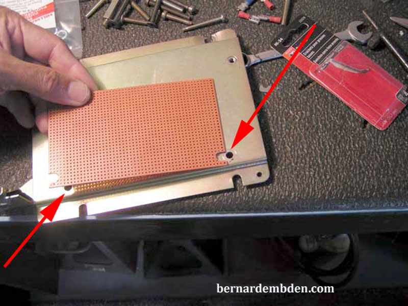
Position fuse box assembly to mounting plate and drill two holes that correspond to the two holes on the fuse box side supports. (red arrows photograph below). These will be the stand offs.
This project requires that the wires be connected underneath the fuse boxes. I wanted to make sure that the metal mounting plate could not inadvertently come in contact with the fuse box wire blade connections. I needed an insulator. Any good non-conductive material will work here. Do not use rubber. This insulator needs to be hard enough so that an inadvertent wire end cannot puncture it. I used Bakelite.
Why? Because I had Bakelite.
Cut to size. Make the size of the insulator slightly larger than the fuse boxes which will require the Bakelite to be notched.
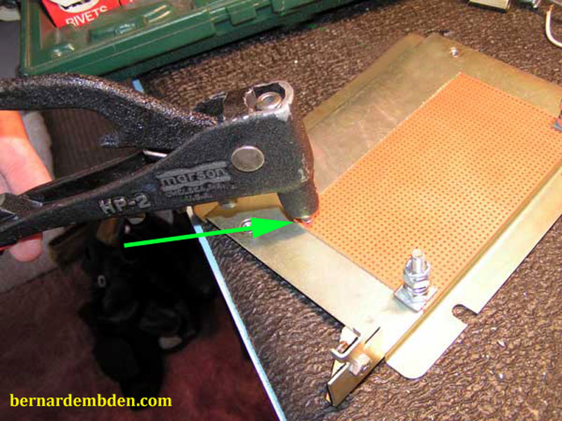
Source two one inch long bolts and nuts as stand offs. Using these bolts and washers (blue arrows) attach the Bakelite to the mounting plate using the standoff holes drilled earlier.
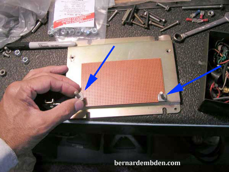
To ensure that this insulator would not move I also riveted the top of the Bakelite to the mounting plate. (green arrow).
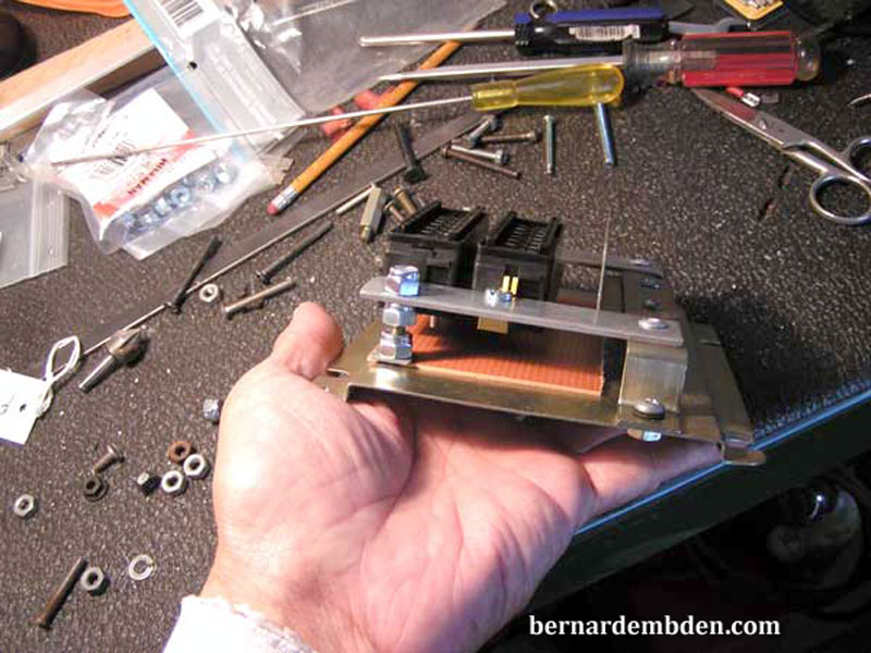
Position fuse box assembly onto the mounting bracket. Use two additional nuts on the stand offs, below the side supports, to position the assembly at the correct height. The completed assembly, attached to the mounting plate, is photographed below.
Fabricating this fuse panel is a straightforward project. The challenge is installing It.
