
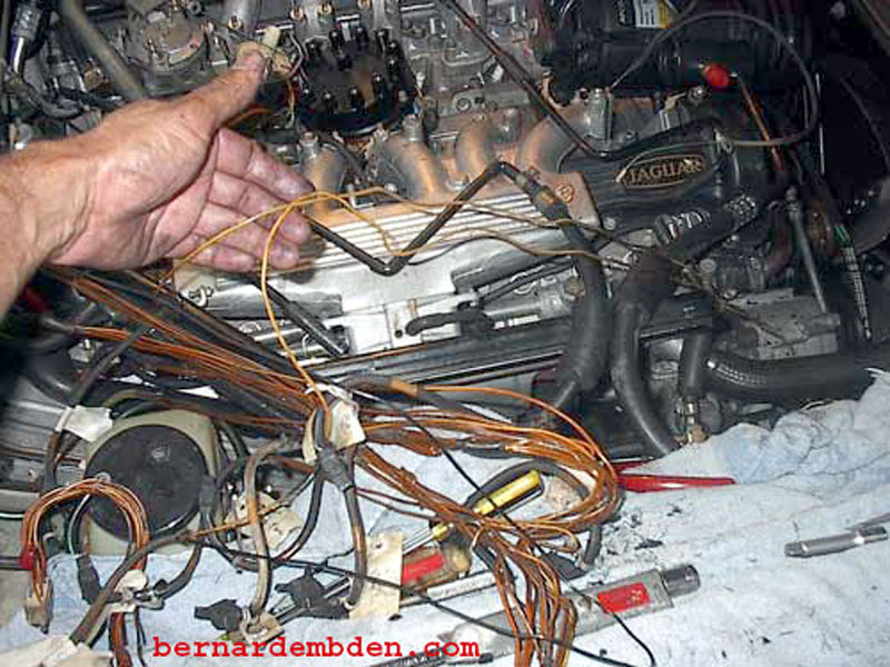
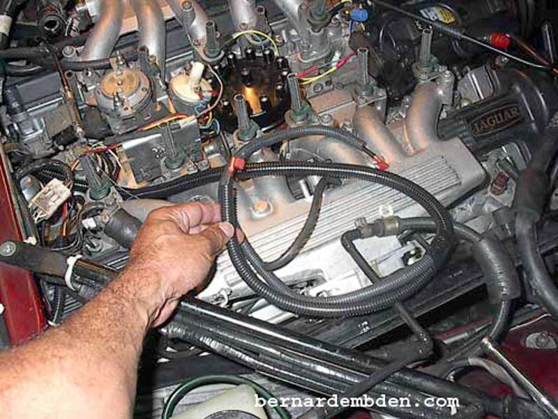
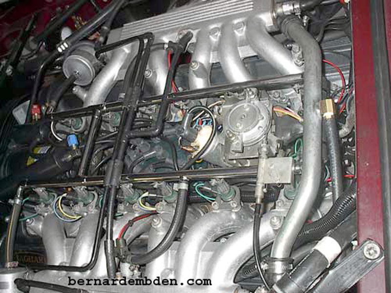
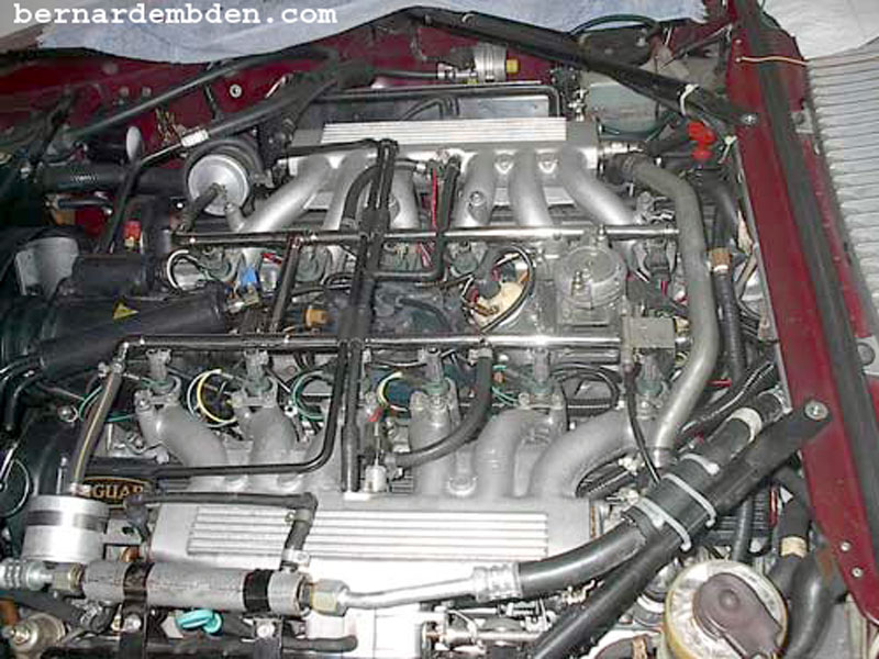
My 1978 XJ-S was now twenty-five years old. Every time I moved the Fuel Injector harness, which resides in the Death Valley "V" of the V-12 engine, it sounded like breaking spaghetti. I could see broken rubber boots, missing insulation and bare wire at many of the fuel injector connections. Finally, I noticed one bank of the engine running slightly richer that the other for no apparent reason.
The time had come to rebuild the Fuel Injection harness and re-furbish the fuel injectors.
I removed all the injectors and sent them to Linder Technical Services in Indianapolis Indiana. (http://www.lindertech.com/). They cleaned and tested the injectors for $24.95 each. They did not charge me for the two cold start injectors. The price included new injector seals and hoses. I had 7mm hose installed on the injectors, which were virtually identical to the factory recommended 9/32 inch hose for the Pre-HE engine.
Examination of many current cars indicated that they have far superior fuel injector harness connections. After doing some research, I was determined to use a connection made by MSD (part number MSD-2400) that was made from ridged plastic, was waterproof and featured a spring clip that locked the connection onto the injector. The available information claimed that this connection was for "Bosh" fuel injectors. These connectors are available from a number of sources including Del City. (https://www.delcity.net) I purchased 16 connectors at "Automotive Engineering Performance Centers" in Clearwater Florida.
I also needed special heat resistant wire. (I don't recommend regular wire in this environment.) My recommendation is 16 gauge Teflon insulated or Cross-linked polymer wire (SLX).
There are a couple of ways to do this project. Plan "A" is the easiest. Remove the old harness, and using it as a guide, build the new harness one wire at a time, essentially duplicating the existing harness.
Plan "B". Use the old harness to draw a detailed wiring diagram. The wiring diagram must include the wire locations at all injectors and the plug. I kept the wire polarity identical to the existing harness. Build the harness based on the diagram taking into account any re-routing or repositioning of the harness. Because I intended to lift the harness off the engine's "V" and separate the harness around the A/C compressor, I went with plan "B"
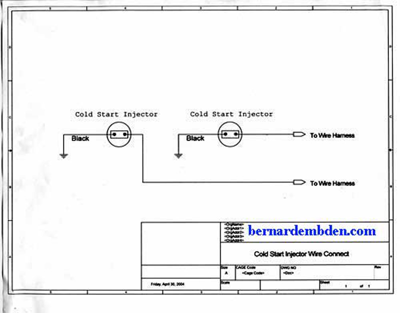
The cold start injectors' bypasses the Amplifier plug and connects directly to the main wiring harness. As the wiring diagram below shows one side is grounded and the signal side actuates based on the thermotime sensor.
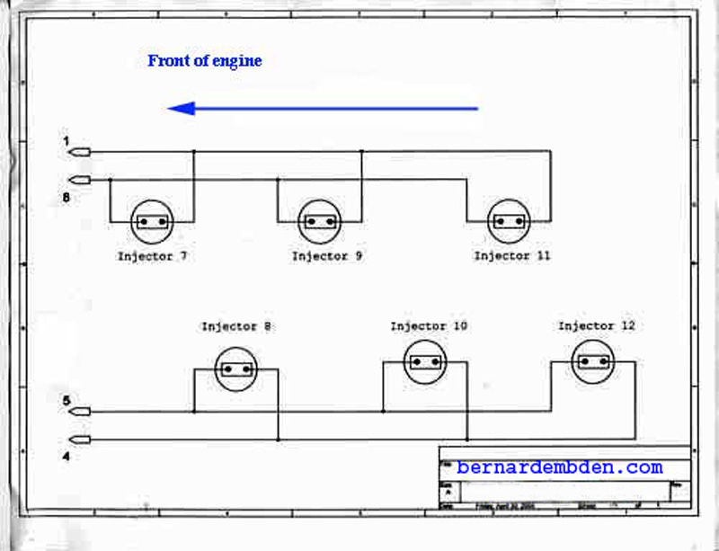
The V-12 fires injectors in banks of three. As the following schematic illustrates, four wires are responsible for each bank.
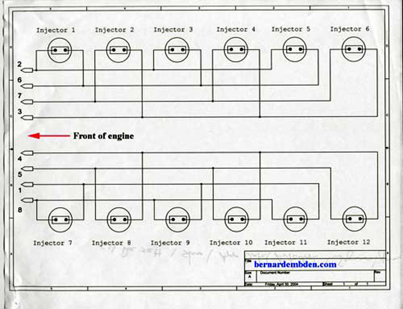
Wiring diagram for all twelve injectors. The wire numbers correspond to the amplifier plug wire numbering methodology.
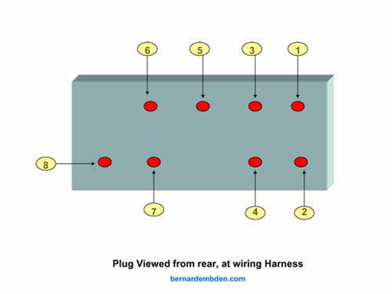
Pictured below is a diagram of the rear of the amplifier plug. (the end with the wires) Any numbering methodology can be used; however it must be consistent with the rest of the fuel injection harness wiring diagram.
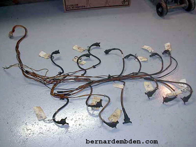
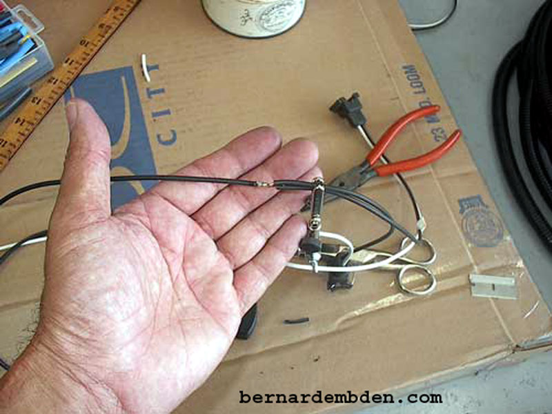
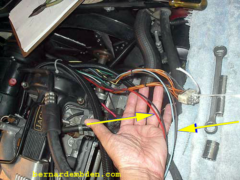
Tag all injector connections and remove the old fuel injector harness. It was a miracle that the car was still working. It looked and felt like wire melting on a brutally hot V-12 engine for the last 25 years. It literally started to fall apart in my hand. (photographs below)
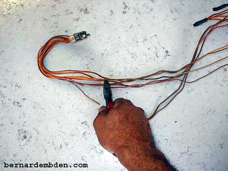
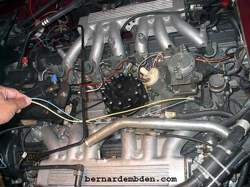
You have carefully and accurately drawn your wiring diagram based on the harness and amplifier plug. You have checked it twice. You are confident that it is absolutely correct. Now you can cut the wires at the plug. (photograph below). Leave enough slack to connect the new wires.
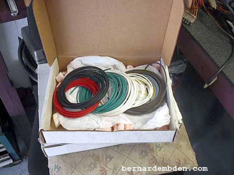
Ed Sowell had completed a similar fuel injection harness rebuild project and was kind enough to send me approximately 100 feet of SLX wire for his cost. The different colors are not necessary for this project; however they do reduce the wire identification process.
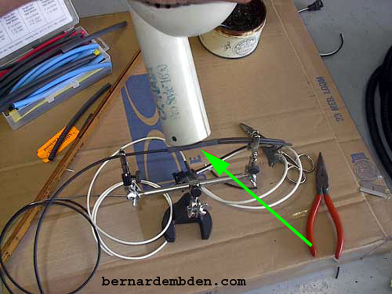
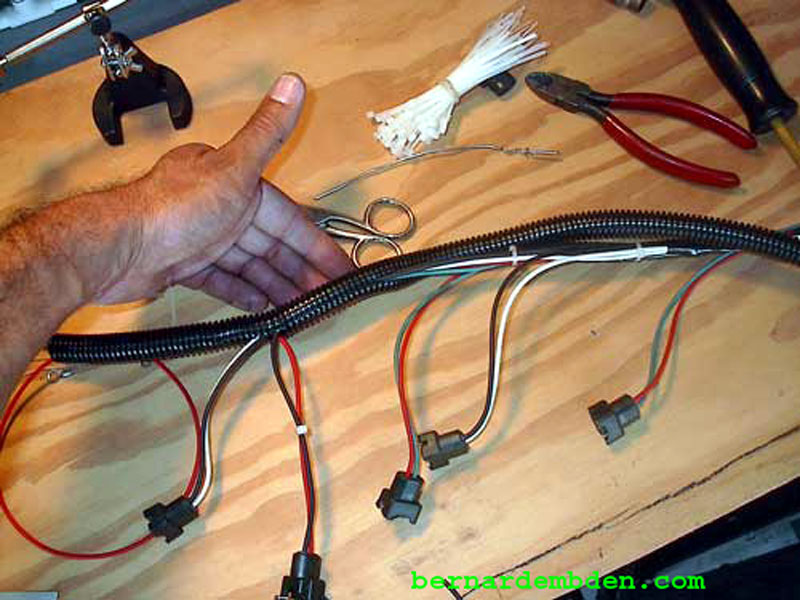
Be prepared to replace all the wires that are routed across the engine. They include the air temperature sensor, A/C, coolant temperature sensor, cold start injectors and thermotime sensor leads. Pictured below is the rebuilt A/C and coolant temperature harness.
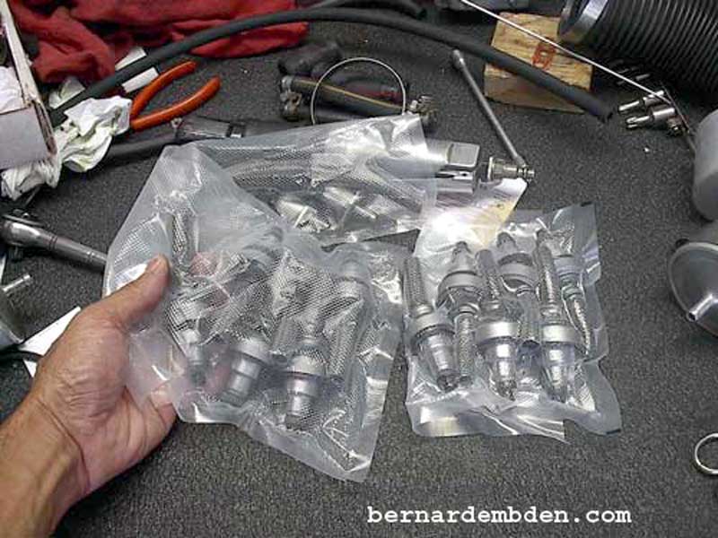
Pictured below are the refurbished fuel and cold start injectors from Linder Technical Services. They arrived sealed in plastic with new seals and hoses.
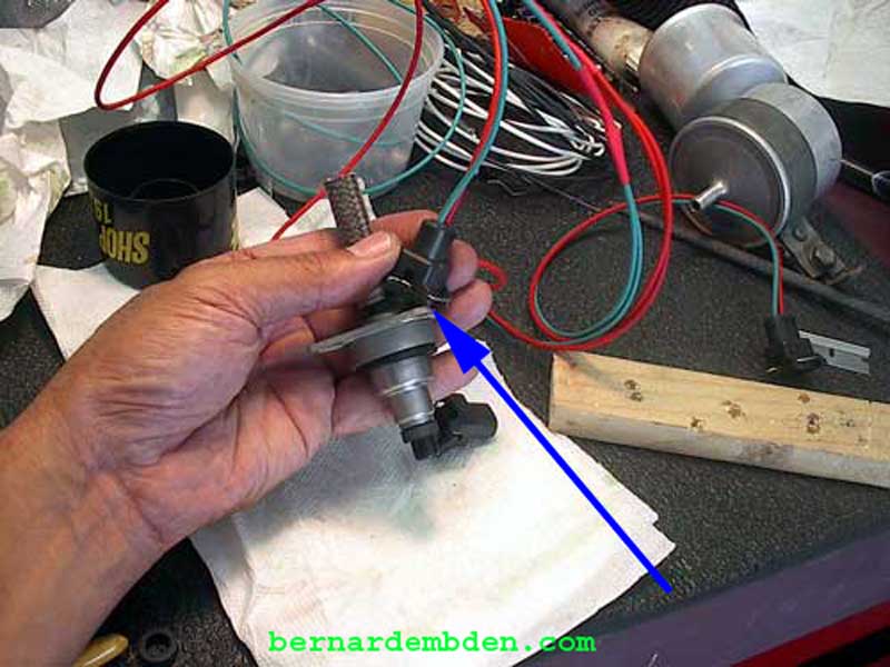
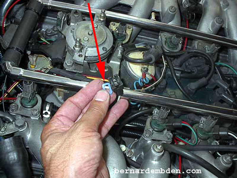
A MSD EFI Injector connector was trial fitted to a refurbished injector and immediately there was a problem. As pictured below, (blue arrow) the mounting bracket prevented the connector from fully seating on the injector.
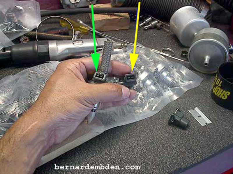
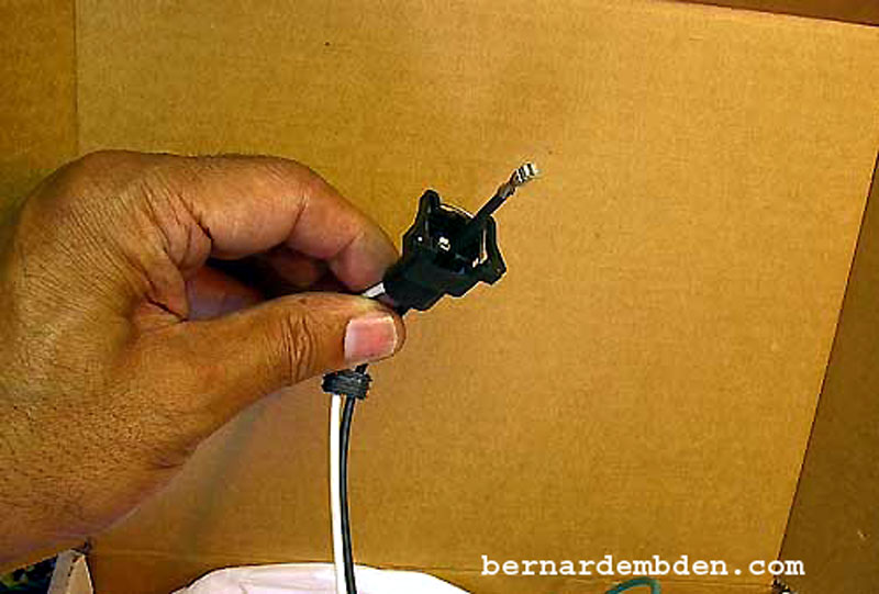
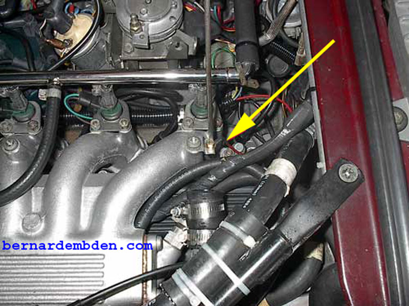
Photograph below. It got worse. The new injector connector would plug into the cold start injector opening, (yellow arrow) but not in the regulator injector. (green arrow) A closer examination revealed that the regular injector opening was slightly smaller than the cold start injector opening.
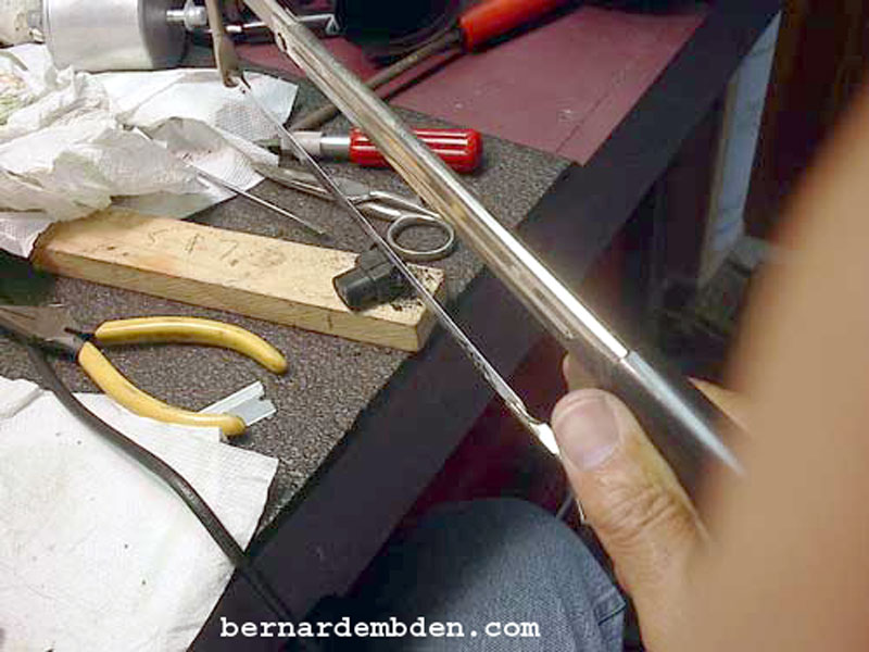
The connectors would have to be modified. In the photograph below, I cut off the part of the connector that holds the spring clip.
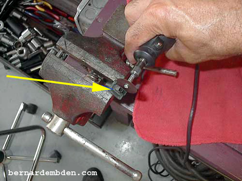
I used a rotary tool to remove material from the center plug until it fits in the injector. Be patient, material is removed a small amount at a time with trial fittings to the injector after each removal. In the picture below (yellow arrow) the shoulder of the plug has been removed for illustration purposes only.
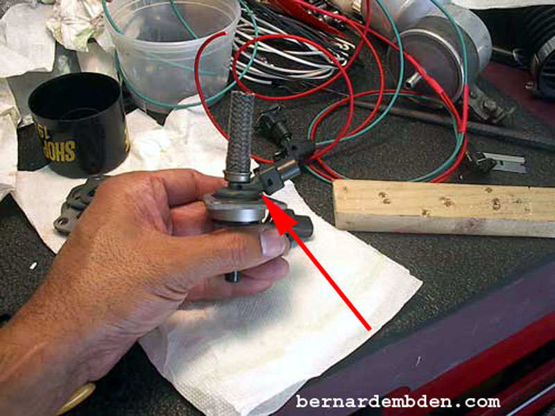
As the red arrow in the photograph below indicates, the connection is now perfect. Only eleven more to go.
First, push the wire through the rear seal of the connector and strip a small section of the wire's insulation. Using the proper tool, crimp the wire to the connector. A pair of pliers can be used as an substitute.
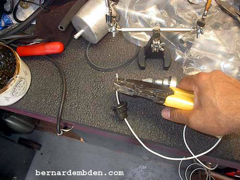
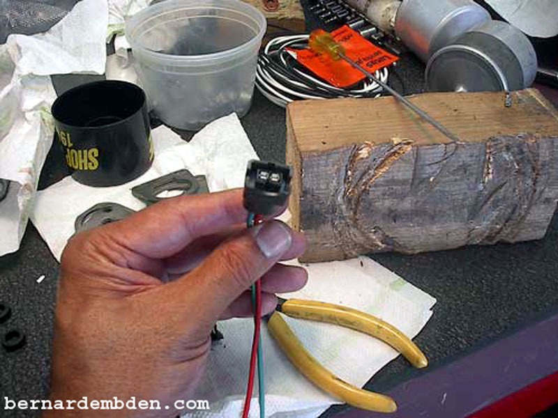
Using a device to hold the wire, (red arrow photograph below) solder the connection. Place the wire at an angle as the photograph indicates, so solder will not migrate into the connecter.
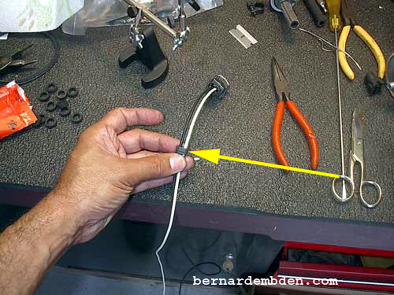
Push the watertight real seal of the connector (yellow arrow photograph below) flush into the connector.
First fuel injection connection completed. You know the drill, eleven more to go.
Duplicate for the cold start injectors. Note that the cold start injectors do not require any modification of the injector plug.
Using the wiring diagram, solder the injector wires and heat shrink all connections.
Use the engine as a template to get exact wire lengths and injector locations based on where the harness will be installed.
Once the main harness wire connections are complete, trial fit the two cold start injector connections to determine wire lengths.
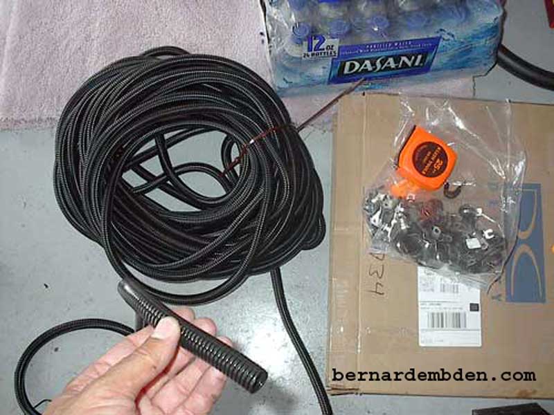
Photograph below. I purchased from Del City 100 feet (minimum order) of special high temperature loom and aluminum clamps for this project.
Complete the harness with tie wraps and then tuck the wires into the temperature resistant loom.
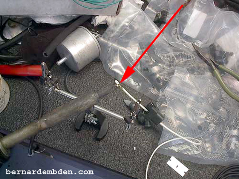
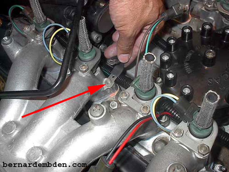
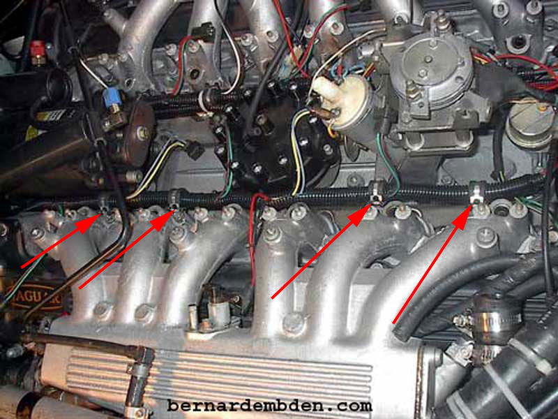
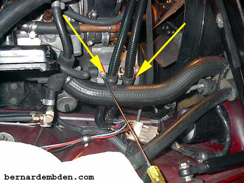
You want to get the harness off the engine. Part of the reason these wires deteriorate over time is because they reside in "Death Valley". I decided to lift the harness off the engine by installing aluminum clamps along the intake manifold bolts. (red arrows photographs below)
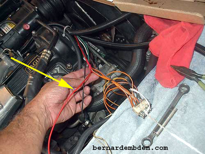
Install refurbished fuel injectors to the fuel rail and install rail. Install the fuel injector connector waterproof seals. (red arrow photograph below).
Make sure to connect the cold start injector ground wires. (yellow arrow photograph below).
I built the fuel injector harness as two separate engine banks. I briefly considered routing the left bank in front of the A/C compressor back to the amplifier plug, however I discarded that idea as having no significant advantage. The original routing, underneath the A/C compressor, not only resulted in better "packaging", but it looked better.
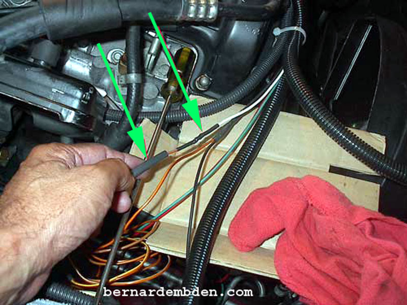
After soldering the harness to plug connections, use double wall shrink tubes or use two shrink tubes as the photograph below illustrates. (green arrows).
In order to get the wire lengths correct, I did the solder connections of the harness to the plug on the engine. In addition, this project afforded me the opportunity to add test ports to the fuel injector harness. I bridged each signal wire from the amplifier (yellow arrows, four in total) and terminated them at a test block. This will allow me to test the pulse duration of each three banks of injectors. (This complete project is covered in another link of this website.)
In any project, details make the difference. After I completed all connections I secured the two looms by fabricating a bracket that bolted to the rear thread of the alternator's top bracket. I then secured the looms with two clamps. (yellow arrows photograph below).
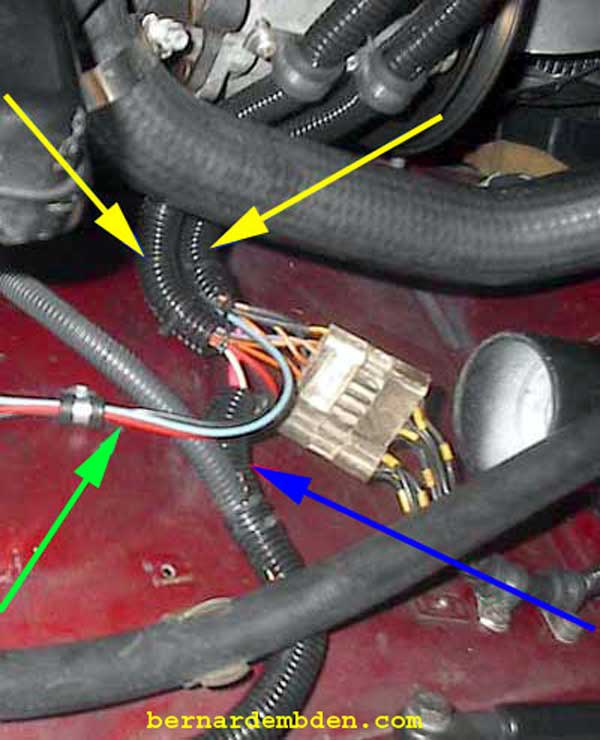
In the photograph below. I combined the two separate looms (yellow arrows) into one harness at the amplifier plug. The green arrow identifies the wires to the injector test block. The blue arrow identifies the cold start injector wires.
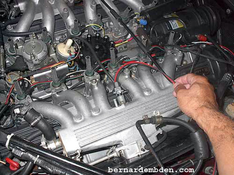
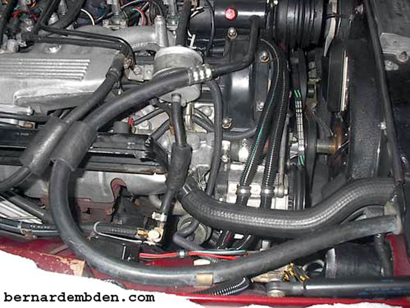
Project complete. The harness looms are secured and routed properly below the radiator hose.
Make sure all fuel injector connections are secure. If injectors have been refurbished, tighten clamps. Start engine, check for leaks. Drive safe.
Expect to spend a couple of days on this project. The results are well worth the effort.
On final thought. Get the right connectors. Because they had to be modified, there was no advantage to using the MSD-2400 connectors.
