
This is a project that I have thought about for some time. Even though you cannot easily quantify the benefits of this modification, common sense indicates that the engine is more effective breathing cold air than pulling in the hot dirty air from under the hood. My first thought was to pick up the outside air above the radiator support. However I kept going back to one simple premise. If I could do a "clean sheet" cold air intake system, where is the most logical place to pick up the outside air?.
For me the answer always came back not to "above the radiator support", but to the flat engine compartment panel behind the headlamps. This would allow not only for the most effective air intake, but also the best engine packaging.
There have been cold air modifications using this location, however they all attempt to feed cold air via the space around the headlamp assemblies by making a secondary hole in the double (boxed) panel behind the headlights. With standard US headlights this concept has some merit. In my case, my Cibie lights completely blocked the rear of the headlamp housing. The objective was to develop and implement a more effective cold air solution. That meant sourcing cold air from in front of the radiator.
First, remove the hood. This took me seven minutes using my custom designed hood removal pulley setup.
Next remove the radiator banjo bleed pipe and the top radiator support. I also removed the radiator and both front wheels.
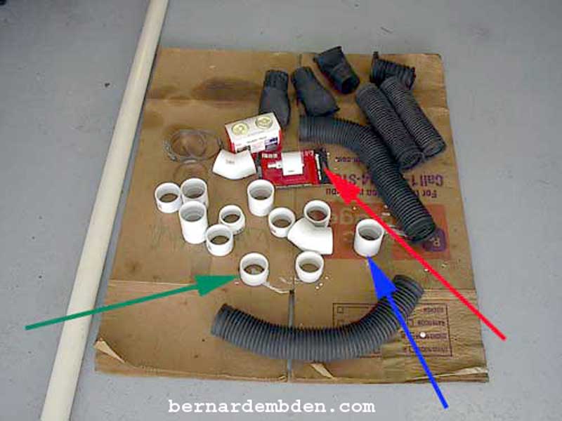
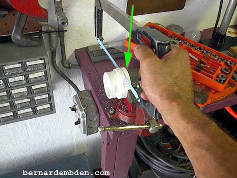
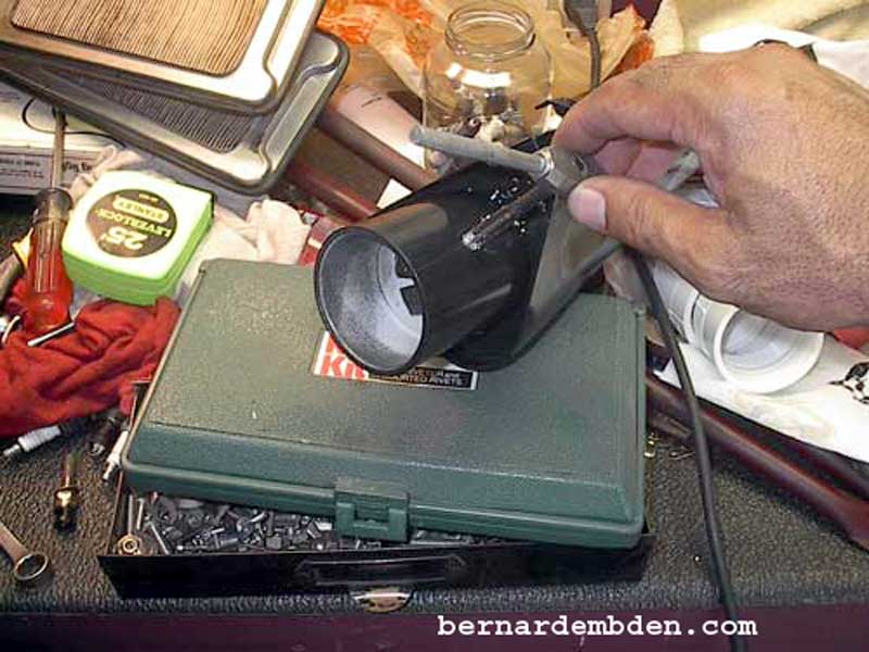
Pictured below are the parts needed for the project. (I always buy more than I need). The ducts were sourced from the junkyard. The PVC hardware from Home Depot. Note the 2.5-inch inside diameter (ID) drill (hole) saw (red arrow). Do not buy a cheap hole saw. Be prepared to spend approx. $20 to $25 dollars US for a decent metal hole saw. The PVC screw adapter (green arrow) fits inside the PVC collar (blue arrow) All PVC fittings are 2.5 inches ID, a significant improvement over the stock 1.5 inch air cleaner intake horn.
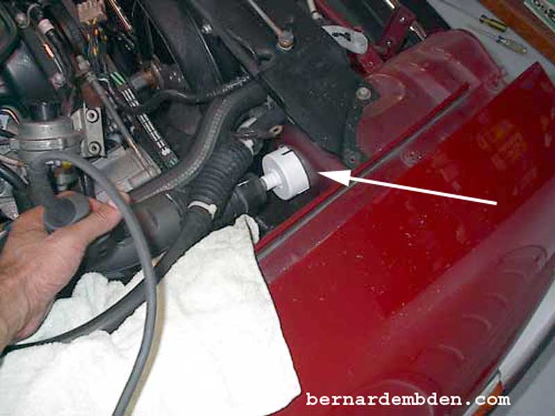
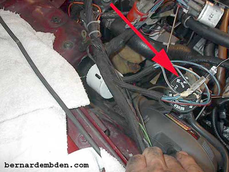
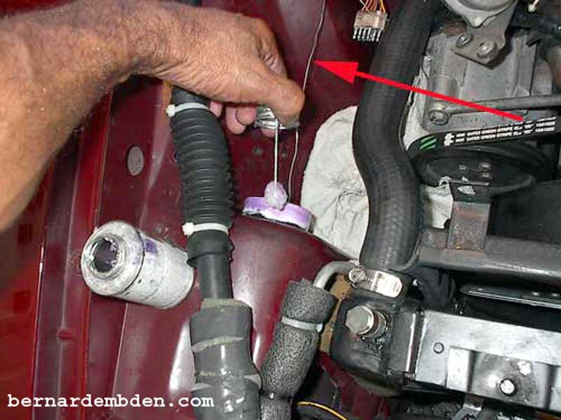
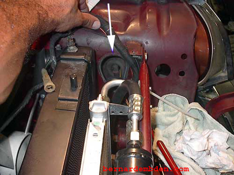
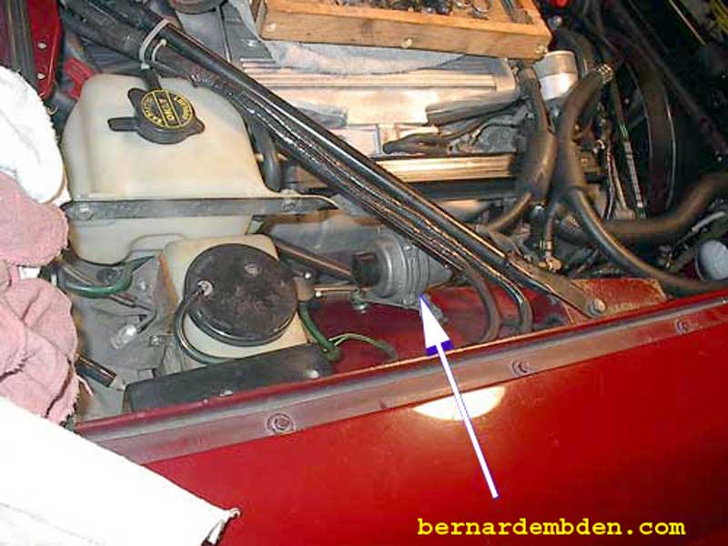
Disconnect battery. Remove manifold pressure sensor. Drill a pilot hole and then a 2.5-inch hole approx. one inch from the top and centered from both sides. (white arrow photograph below)
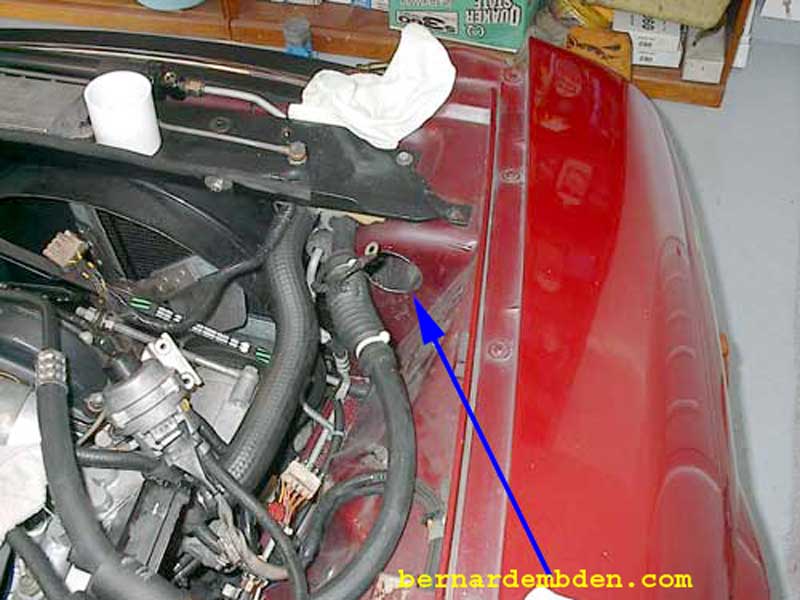
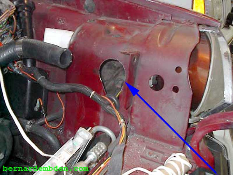
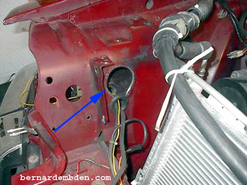
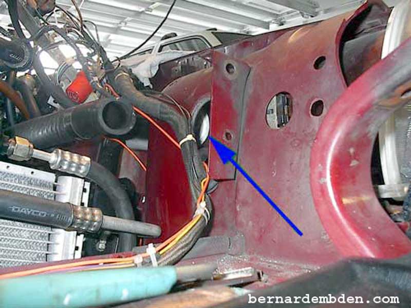
There is nothing like a 2.5-inch hole in the engine compartment to get me motivated. Note that this hole (blue arrow photograph below) does not go all the way through to the headlight opening. There is another panel behind the headlight.
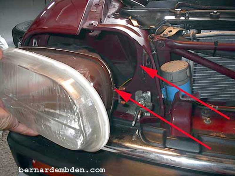
The photograph below shows my Cibie light removed. The second panel is at the rear of the headlamp assembly. Note the fit (red arrows) between the light assembly and the headlight opening. When installed there is virtually no space between the assembly and the opening. A small existing opening at the side of the headlight opening would provide some air ingress, however I don't believe it would be effective.
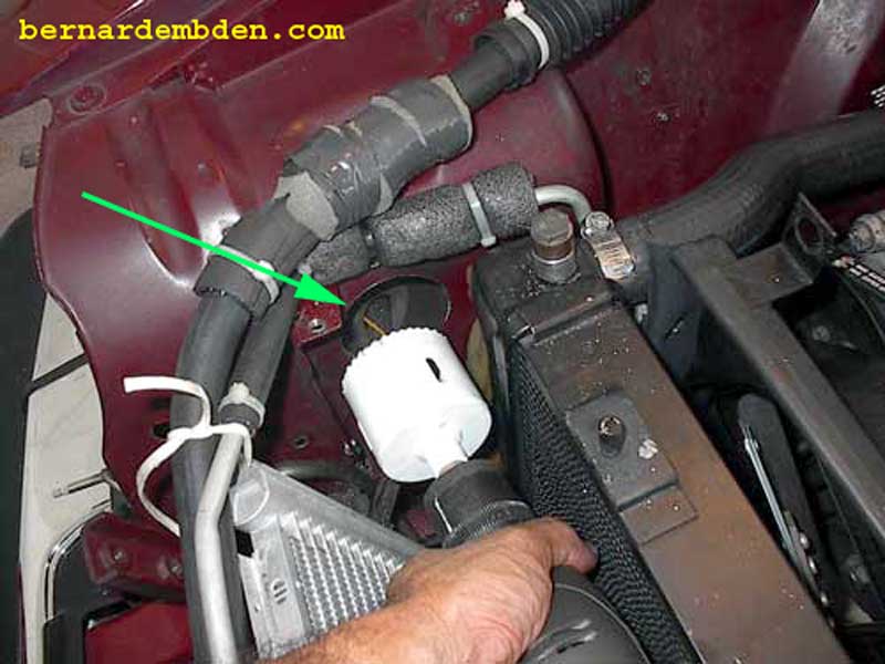
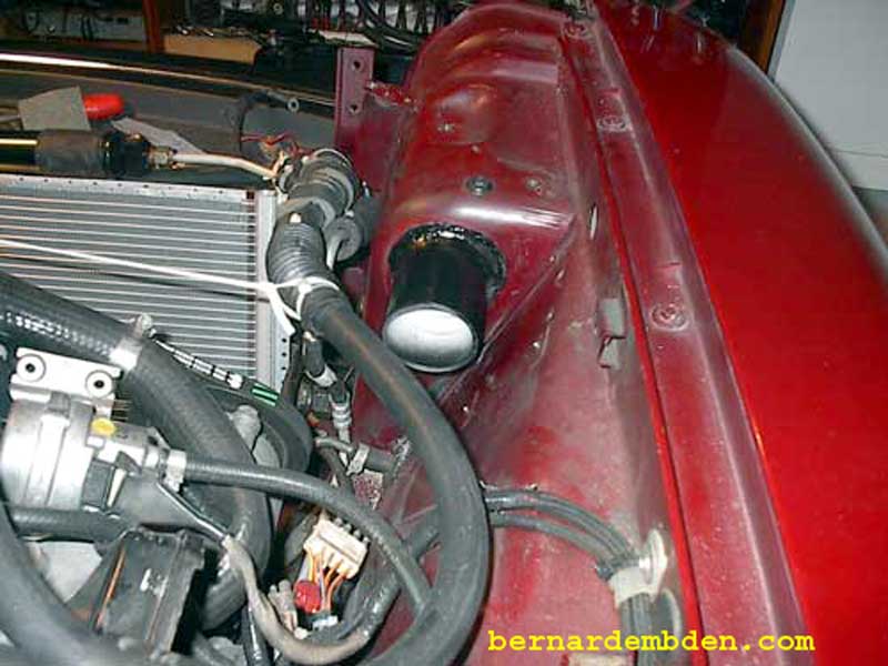
Remove the relays cover, relays and relay bracket from the left side of the engine. Remove the nuts for the expansion tank and move it away from the side of the engine compartment. (red arrow photograph below). Carefully drill a 2.5-inch hole in the flat panel, duplicating the location of the right side.
The box section behind the headlight tapers towards the inside of the headlight assembly. Drill a 2.5-inch hole 1/2 inch above the existing hole for the cable harness. Either remove the radiator or protect the radiator and the A/C condenser. Drilling large holes in metal can be unpredictable.
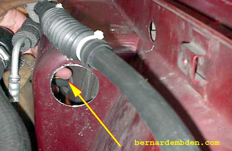
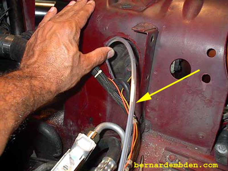
Note the unrestricted access between the two holes. (yellow arrow photograph below). This exactly what I wanted. Cold air to be picked up without restriction in front of the radiator.
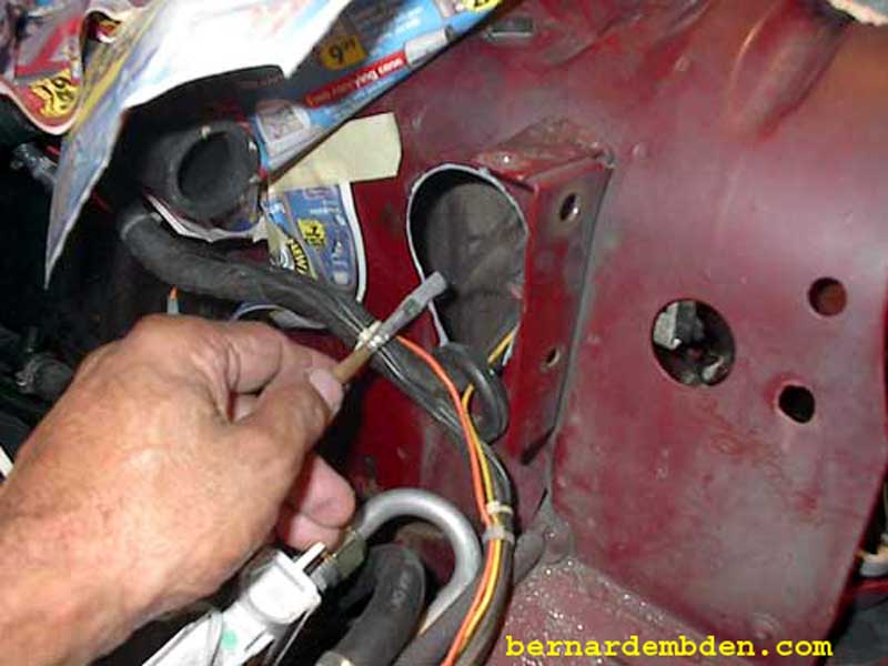
Remove the material between the new hole and the existing wiring harness opening with metal snips.(yellow arrow photograph below)
Duplicate the hole and metal removal on the left side of the radiator opening.(blue arrow photograph below)
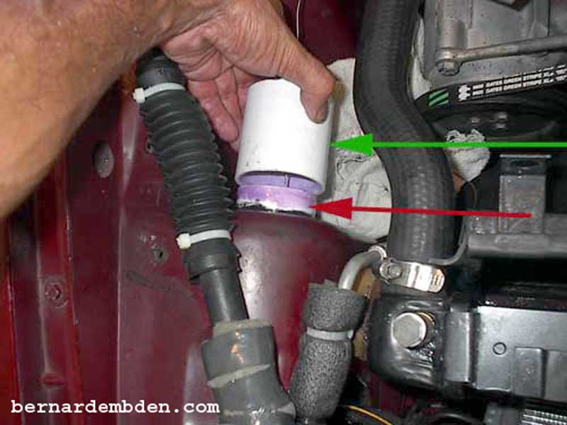
(Green arrow photograph below) Cut approx. half the thickness off the ring of the PVC adapter.
The PVC adapter is 2.5 inches ID. The "ring" is larger than the pipe. It will not fit through an unmodified 2.5" hole. By modifying the hole and cutting the PVC adapter ring, you can now insert the PVC adapter through the enlarged hole inside the radiator opening.
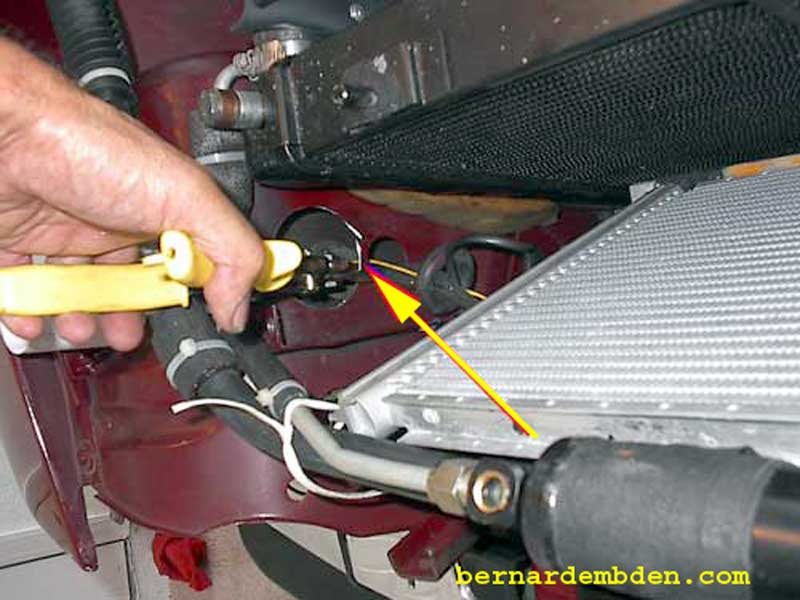
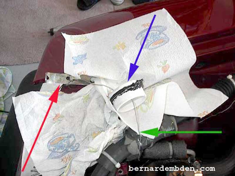
In the photograph below. I used a piece of scrap metal and wire to fabricate a simplistic "holding tool" with the wire tied to the metal strap. (red arrow). Run a bead of silicone around the PVC adapter. Note that the adapter "ring" (blue arrow) is slightly larger than the adapter. This will prevent the adapter from being pulled through the 2.5-inch hole. Install the "holding tool" through the PVC adapter and run the wire (green arrow) through both 2.5 inch holes.
Slip the wire (red arrow) through the PVC collar and tie off firmly to any support within the engine compartment. Apply PVC cleaner and cement to the outside of the adapter and inside of the collar.
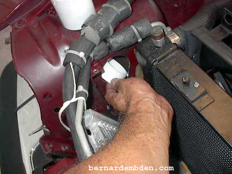
Force the collar (green arrow photograph below) over adapter (red arrow) with a twisting motion until it bottoms against the engine compartment sheet metal. The silicone should push out as the collar is seated.
If you are familiar with PVC you know that you don't have a lot of time to do this. If the collar will not seat, remove immediately, or you will have to saw it off. It might help if you have someone with small hands (wife) hold the adapter instead of the "tool".
Once it's on it is permanent.
Duplicate process on the left side of the engine, but use a 45-degree elbow. This is necessary to clear the neck of the expansion tank. I ran a bead of automotive seam adhesive around both PVC collars and then painted the intakes black. Seam adhesive, available from any good auto body supply house, is not necessary for this project, however it prevented the collars from turning. JB Weld is a satisfactory substitute.
Left air intake completed. (photograph below) Note that the 45 degree elbow clears the expansion tank.
Photographed below. Right air intake completed
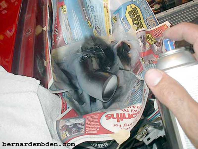
Prime and paint the holes in the radiator/grill opening
You don't want these holes to look as if you butchered them in. The project should not only be effective, it should look good. I installed clear door edge trim over the edges of the openings.(yellow arrow photograph below)
Clear door edge install completed. (Blue arrow photograph below).
Note the unrestricted air path in the left air intake below.(blue arrow)
Location of the left intake opening (white arrow) with the radiator and condenser installed
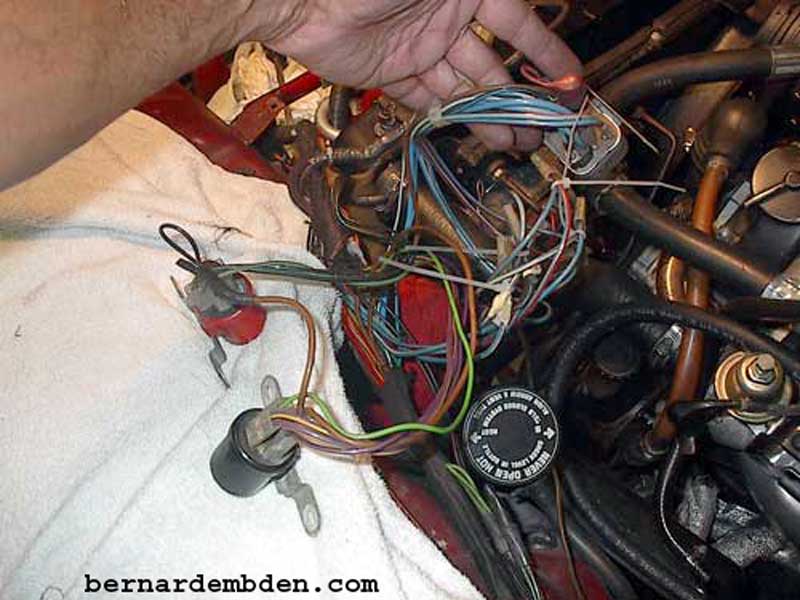
In the photograph below, I decided not to "just move" the relays from the left side of the engine. I stripped back the wire loom and tagged and removed the wires. (If you are not comfortable doing this, then remove one wire at a time).
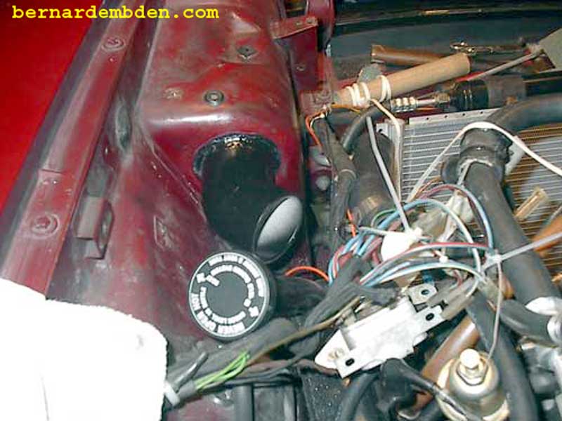
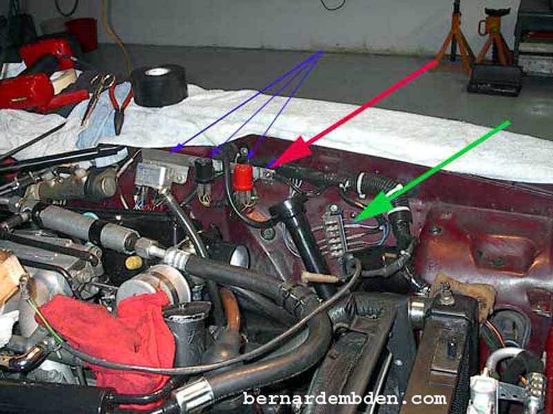
I modified and then used the original relay bracket to mount the relays on the left fender support. (small blue arrows photograph below). Redo the wire loom. I also moved the ground connection from the upper radiator support to this bracket. (red arrow). The green arrow shows the fuses for the headlamps etc.
I relocated the manifold pressure sensor to underneath the right engine bay support. (white arrow photograph below)
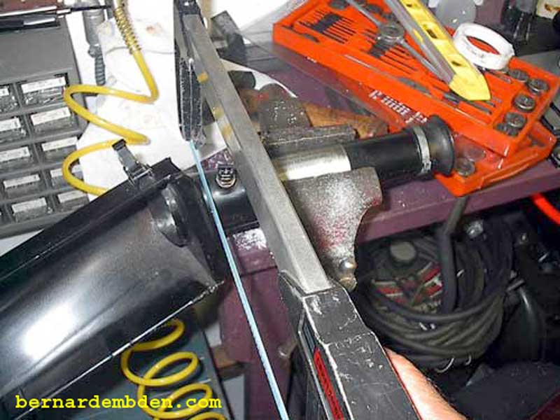
The next step is to transition the air cleaner opening to the new cold air supply. Start by cutting the air cleaner intakes one inch from the air cleaner assembly.(photograph below).
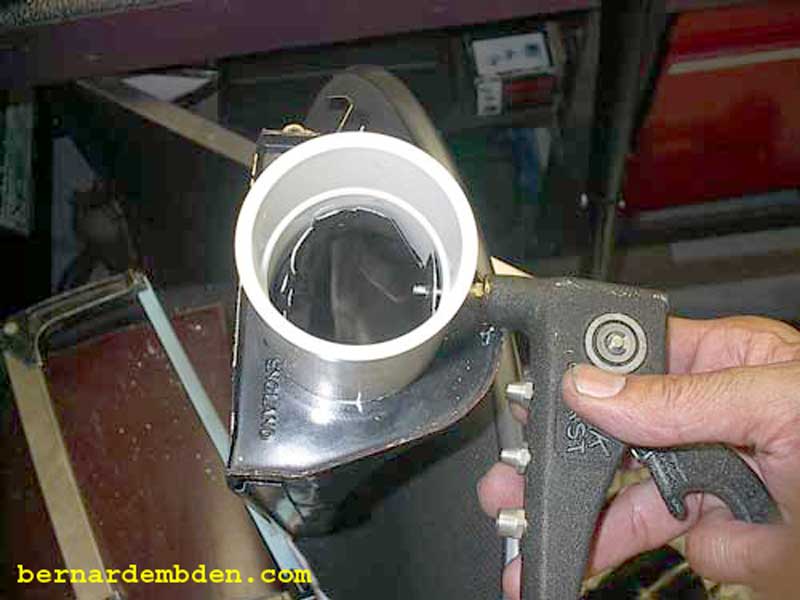
Using tin snips I made several "cuts" around the circumference of the air intake. Using a needle nose pliers I spread the intake "tabs" out to the PVC collar and riveted the collar to the metal "tabs" at three locations.
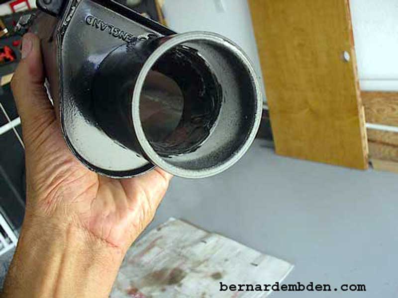
Push the non-riveted tabs flush against the PVC collar. Silicone seal the area to finished the assembly.
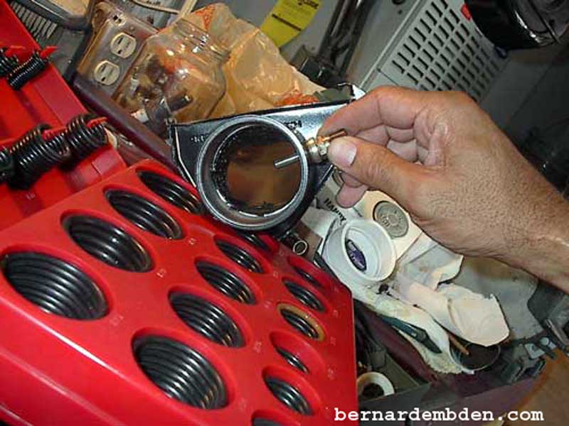
Thread (M8x1.25) the PVC collar for the air temperature sensor. The sensor does not require grounding.
I used a spacer and a generic "O" ring to install and seal the sensor to the PVC collar at the original depth. Hand tighten only.
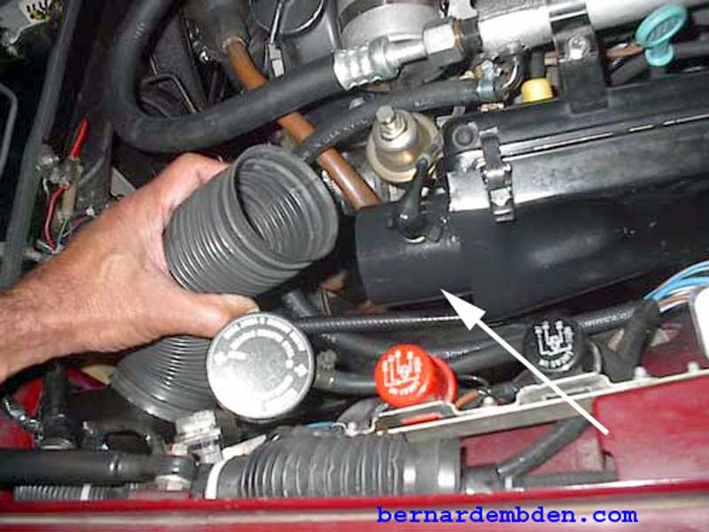
Install left air cleaner assembly. Install air temperature electrical plug to sensor. Install 2.5-inch air duct to modified air cleaner intake (white arrow photograph below) Note clearance of the expansion tank.
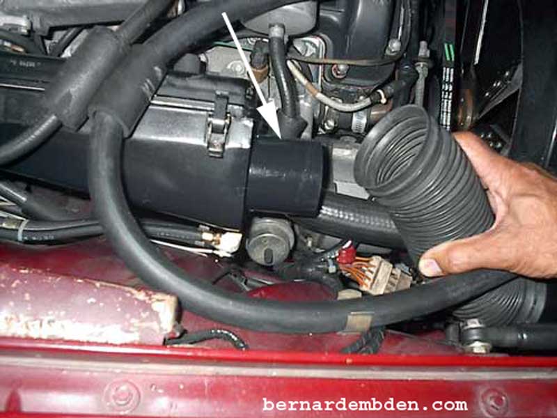
Install right air cleaner assembly and 2.5 inch air duct to air cleaner (white arrow photograph below).
Project complete
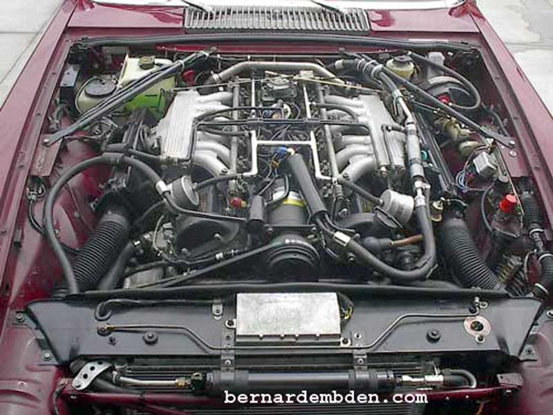
This is a somewhat difficult and intimating project. Expect to spend 3 to 5 days. When completed, you might not breathe any better, but your Jaguar certainly will.
