
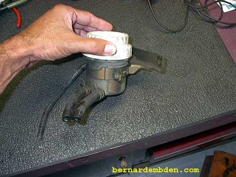
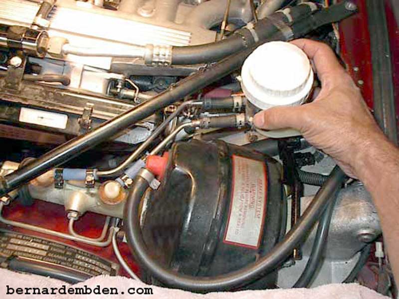
The replacement reservoir (from a 1995 Mitsubishi Eclipse) is almost the same size as the original with fluid exit hose connectors in approximately the same location. Most importantly, it used a far superior method of monitoring the brake fluid level.
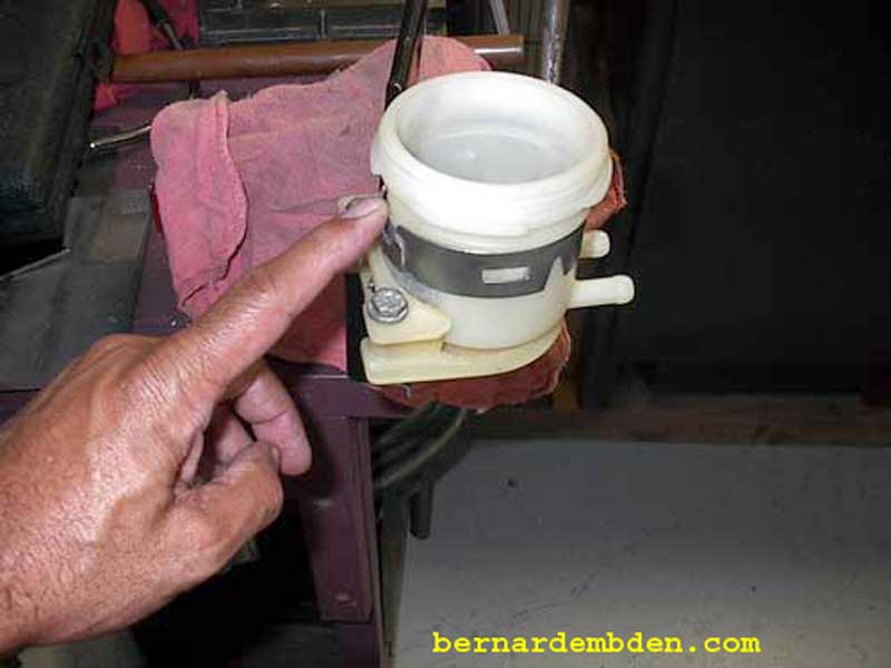
The replacement reservoir (photographed below) was sourced at the junkyard. Make sure you get the bracket, bottom switch, in tank magnet along with the wiring and connector. Junkyards now charge for everything, so I paid $7.00 for the reservoir and an additional $3.00 for the bracket.
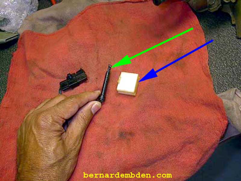
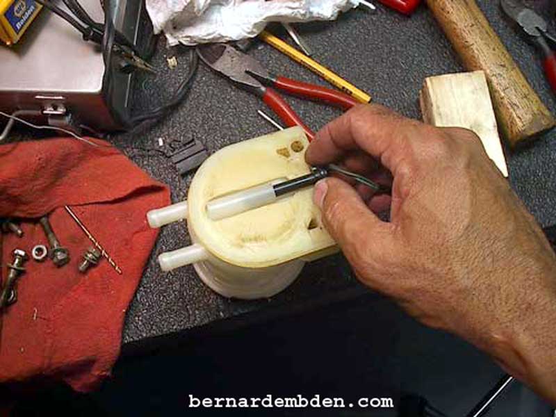
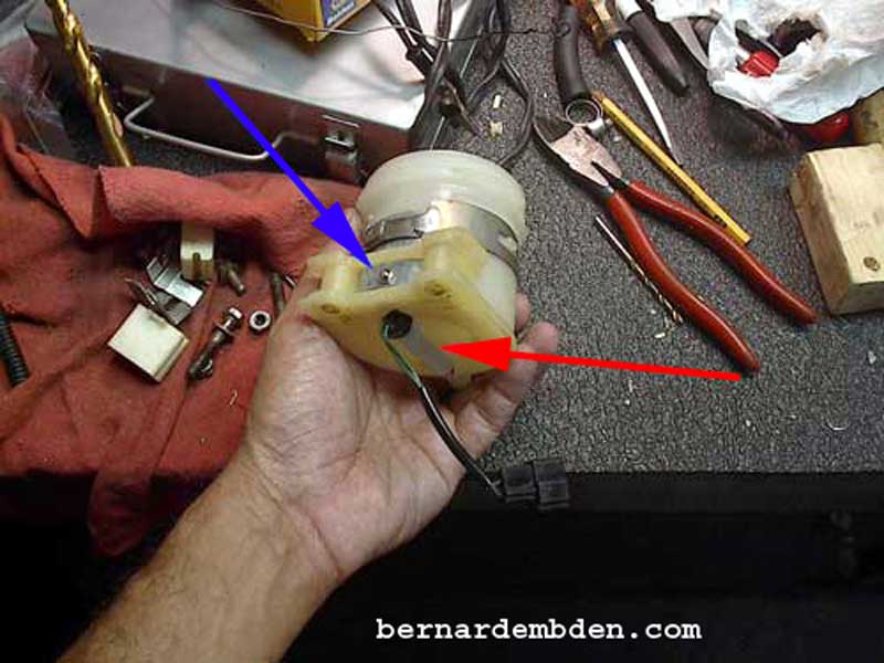
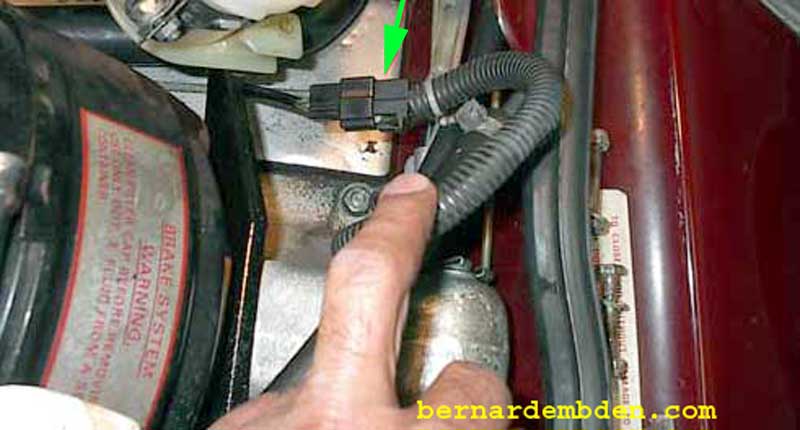
Photographed below are the bottom switch (green arrow) and the magnetic actuator (blue arrow). The switch fits in a tube externally at the bottom on the reservoir. The magnetic switch floats inside the reservoir. When the fluid level falls to a predetermined level the magnet activates the switch. This design puts the sealed switch assembly outside the brake fluid, a vast improvement over the original Jaguar design.
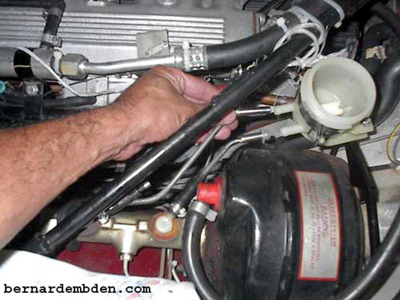
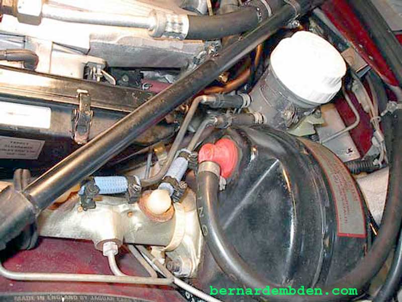
To ensure air does not get into the system, immediately plug the connections to the master cylinder when you remove the steel brake fluid supply pipes.
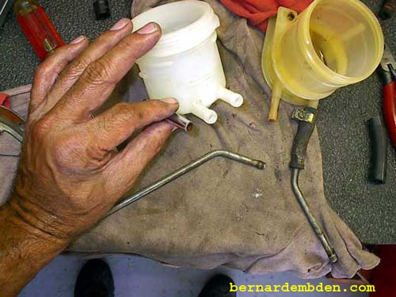
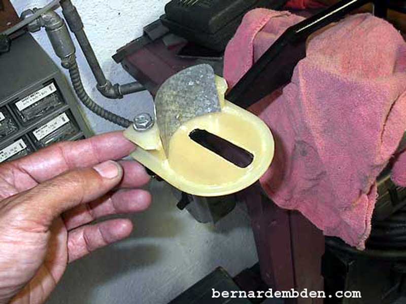
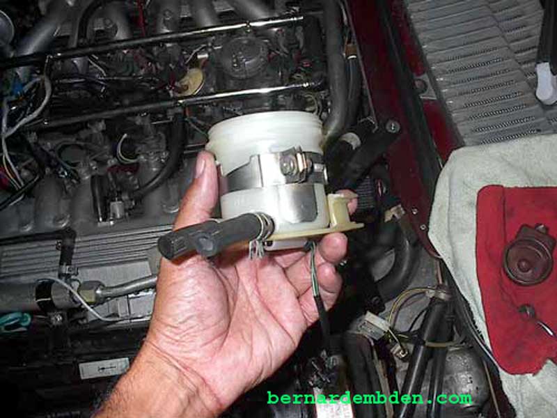
Comparison of the Mitsubishi and the original Jaguar reservoirs indicate how similar they are. The Mitsubishi reservoir is slightly smaller and shorter. Note that the hose connecters on the Mitsubishi reservoir (red arrow) is bigger that the Jaguar reservoir (blue arrow).

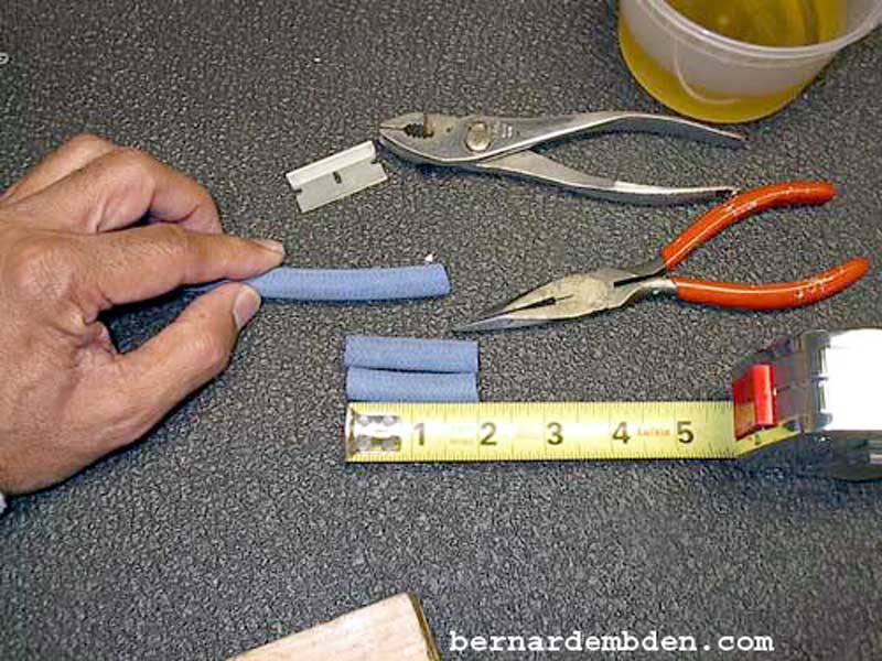
The first challenge was to transition the 3/8-inch Mitsubishi reservoir outlet to the 1/4inch steel pipe that connects the reservoir to the master cylinder. There are a number of ways to do this. Simply using a 3/8 to 1/4 inch fitting and the appropriate hoses would work. For me, this was not acceptable. I wanted to retain the steel pipes. They looked better that hoses and fittings. My solution, modify the steel pipes to provide a 3/8 inch fitting at the reservoir. A 3/8 copper tube, available from any plumbing store, was the exact size O.D. needed for this project.
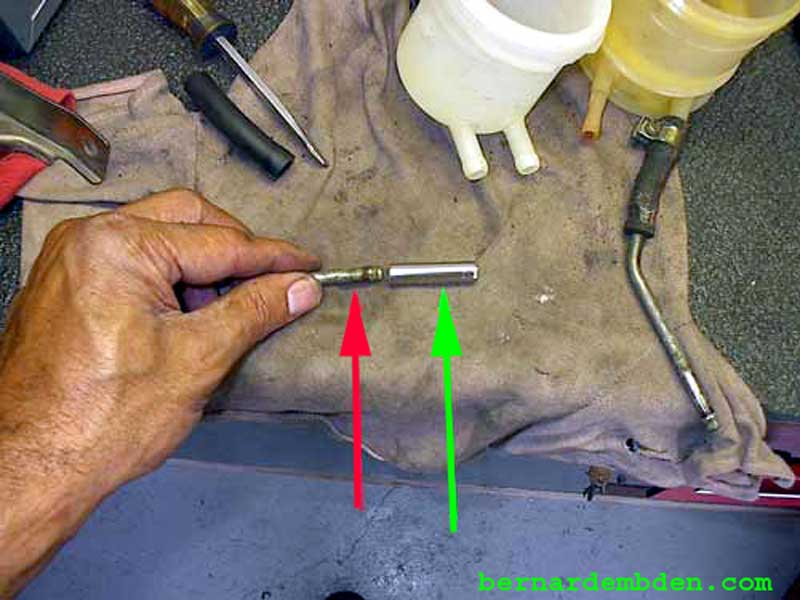
Cut approximately 1-1/2 inch of pipe (green arrow). This would go over the existing steel pipe (red arrow) to give me the 3/8 inch diameter I needed while maintaining the exact length of the original pipe.
My first intention was to weld the 3/8 inch copper tube to the 1/4 inch steel tube. This seemed unnecessary. These are feed tubes, they are not pressurized and I designed the copper tube to go over the steel pipe. It was much simpler to solder the tubes to the steel pipe.
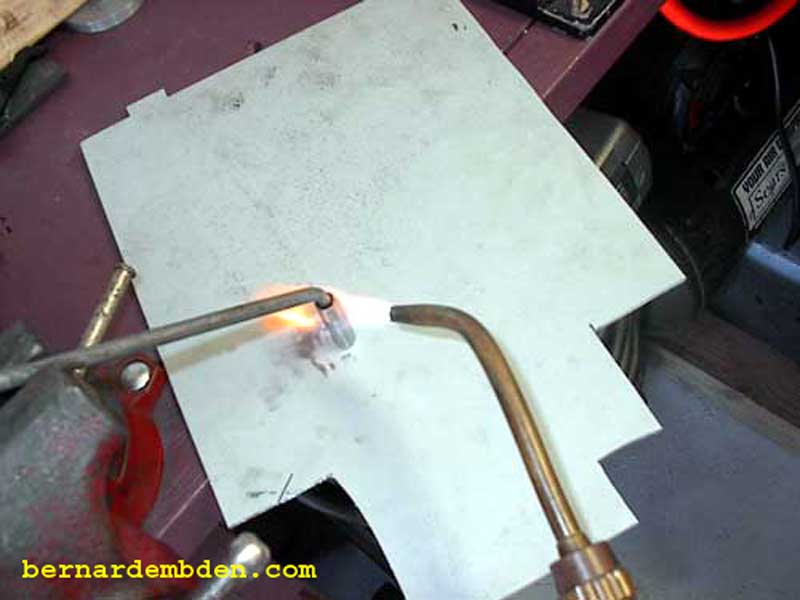
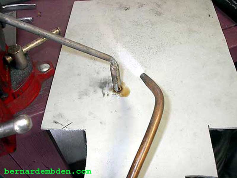
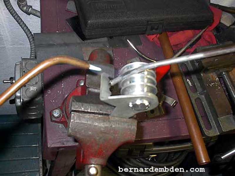
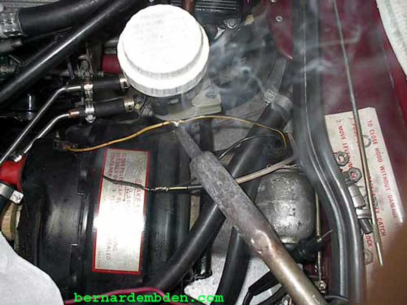
Soldering steel required some expertise. Unlike copper, steel requires more heat, which usually vaporizes the solder. The trick is to clean, flux and tin the steel before the final soldering process begins. I supported the work with a vise and an aluminum sheet (photographed below). Use a low flame, move it constantly while filling the space between the tube and pipe with solder. Take your time on this.
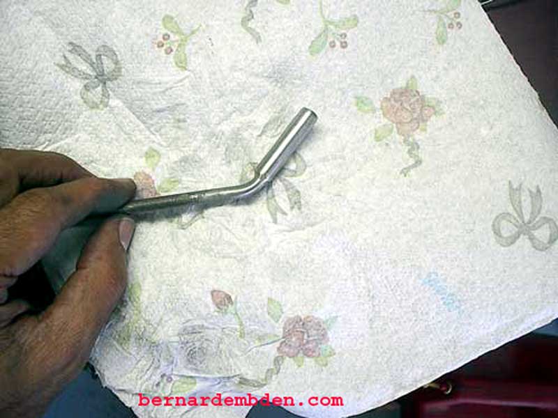
When finished, clean and sand smooth. The finished product must not only hold pressure, but it must look good.
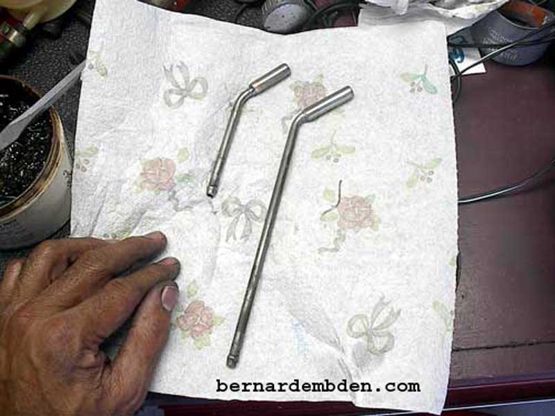
Modification to both steel pipes competed. Note that the longer pipe is reversed. I modified the end that normally attaches to the master cylinder, not the end that attaches to the brake reservoir. This will eliminate one hose bend and allow me to have straight hose fittings to the new reservoir on both steel pipes.
The next challenge was the reservoir bracket. The original Jaguar reservoir has two mounting holes molded in the base which mounts to a bracket bolted on the power brake booster.
Fabricating a simplistic bracket from sheet metal, attaching it to the existing power brake booster bracket and securing the reservoir with an aero-seal clamp was not acceptable. It simply did not meet my expectations of how this project should look.
The Mitsubishi reservoir bracket is designed specifically for its reservoir, with locating tabs that align the bracket to the reservoir. I explored the fabrication of a new bracket from the power brake booster to which I would mount the Mitsubishi bracket. I discarded that idea because I wanted to retain the simple elegance of the original Jaguar mounting bracket.
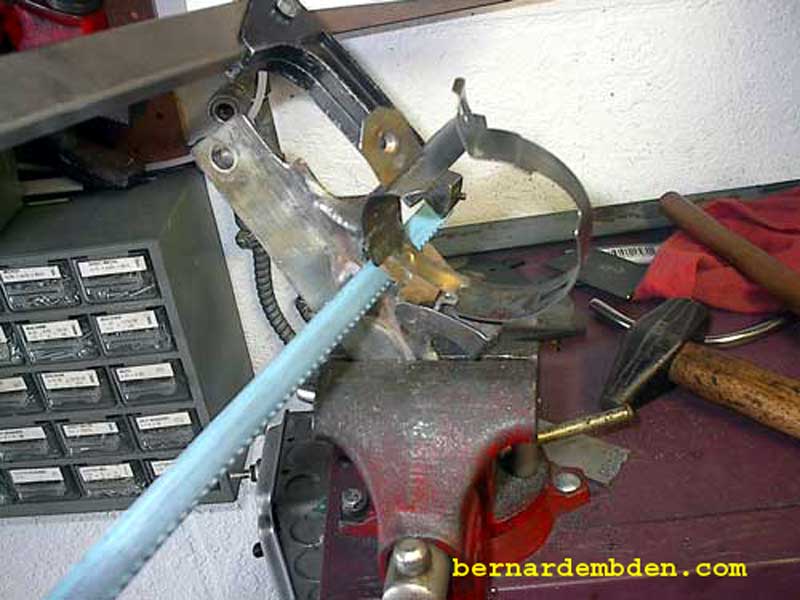
I had sourced the Mitsubishi reservoir bracket fully expecting to use it as an integral part of the install, however only the part that goes around the reservoir would be needed. Using a hacksaw (photograph below) I removed the bracket from its base. Grind the excess metal from the bracket on a grinding wheel.
I decided to use the old Jaguar reservoir as the mounting base for the new Mitsubishi reservoir. (I no longer needed it). First cut the reservoir at the mounting base.

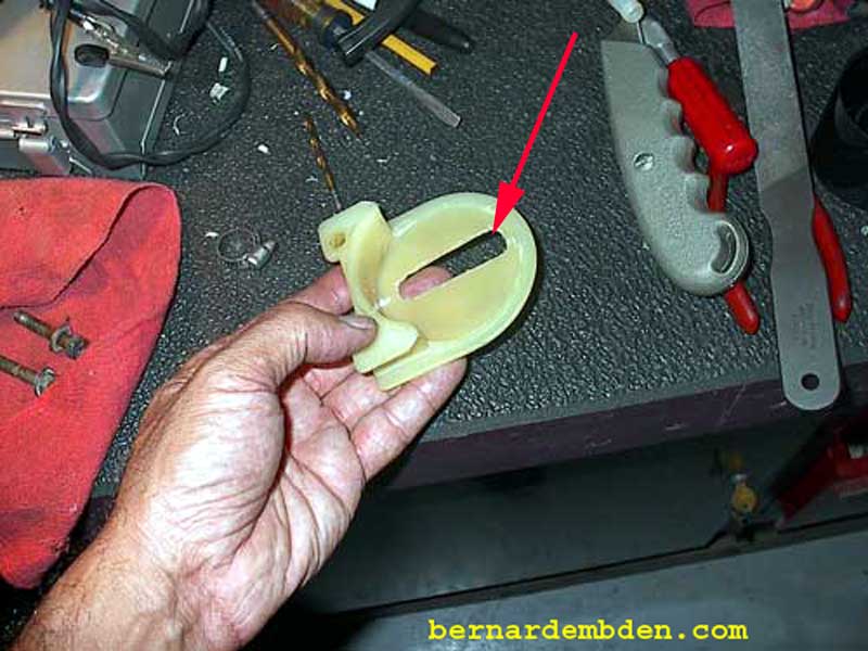
Remove the center divider and approximately 2/3 of the outer ring. In addition, using the bottom of the Mitsubishi reservoir as a guide, cut a slot in the base to allow clearance for the bottom switch mounting tube. When complete the modified base should look like the red arrow photograph below.
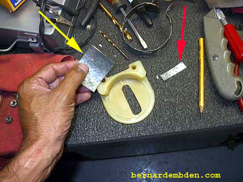
In the photograph below, I used galvanized sheet metal to fabricate a "back support plate" (yellow arrow). The red arrow identifies what will become a "washer" when the support plate is bolted to the modified base.
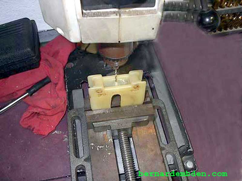
Drill a hole in the center of the modified base to accept the mounting screw.
Using one small screw I attached the back support plate inside the rear lip of the modified base. When complete, visually, this location would be the least intrusive.
Offer Mitsubishi reservoir to the modified reservoir base.


Attach the Mitsubishi bracket that was removed from its base. The finished base / bracket gives me exactly what I wanted. A finished product designed for the reservoir, looks good and uses the original Jaguar bracket.
Turn the bracket assembly upside down and insert the brake fluid monitoring switch.
If brake fluid magnetic float was removed for cleaning, reinstall.
Photographed below is the completely assembled reservoir, customized bracket and brake fluid level switch. The back support plate is attached via bolt and nut (blue arrow). The red arrow identifies the brake fluid level switch.
Prior to assembly install the two rubber hoses. This hoses are 10mm and can be sourced from Mitsubishi. I recommend using spring clamps (instead of screw type) on plastic parts.
Trial fit the steel lines. As discussed earlier, the longer steel line will require modification. I will have to bend the pipe to line up with the master cylinder connection.
I used a tube bender and heat. When bending steel heat is necessary to ensure a smooth bend. Use the flame to massage the pipe as you apply pressure.
The photograph below indicates the proper bend.
Now is the time to carefully examine these hoses that connect the steel pipes to the master cylinder. If they are suspect change them now. Unfortunately Jaguar no longer carries these parts. They are 7mm ID hoses that are designed for non-pressurized brake fluid. I sourced 1 meter (approximately 36 inches) from Bughaus, (www.bughaus.com) a company is Tulsa that sells VW parts. Cost $9.00 US plus shipping.
Cut two lengths of hose 2 inches long and attach to the plastic connections on the master cylinder and the steel pipes.

Clamp hoses using care on the hose ends that clamp to the plastic master cylinder connection.
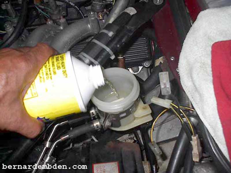
Attach all hoses and add brake fluid. Install cover and lift the reservoir higher than the master cylinder to purge any air that might be in the steel lines.
Bolt reservoir to the original brake booster bracket using the original mounting hardware.
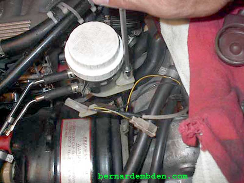
Remove brake fluid level wires from the original reservoir cap. There are 3 wires, the third wire goes to the brake pressure differential sensor mounted in the engine compartment below the master cylinder. Note that the dashboard brake indicator light not only signals low fluid but brake pressure differential as well. Cut and solder the wires to the plug wires sourced with the Mitsubishi reservoir.

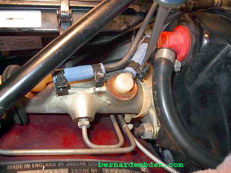
Connect plug (green arrow photograph below). Enclose the wiring in wiring loom and tie-wrap as needed.
Project Complete.
This is not a difficult project. The difficulty is making it look good.
